Volume 24 article 1351 pages: 530-541
Received: Feb 02, 2026 Accepted: May 22, 2026 Available Online: Jul 02, 2026 Published: Aug 17, 2026
DOI: 10.5937/jaes0-65331
ALGORITHMIC MODEL FOR DIGITAL RECONSTRUCTION OF ROTATIONAL MECHANICAL COMPONENTS BASED ON 3D SCANNING
Abstract
The accelerated development of digital technologies, particularly 3D scanning techniques combined with reverse engineering procedures, has enabled efficient digital reconstruction of mechanical components in situations where original technical documentation is unavailable or the component has been damaged during service life. This study presents an algorithm-based model developed for the reconstruction of a symmetrical rotational mechanical component using optical 3D scanning and advanced point cloud processing in Geomagic Design X software. The proposed model addresses three characteristic preservation states of the component: a partially damaged part with locally cracked geometry, a completely damaged part with missing geometric segments, and an undamaged reference part. The reconstruction workflow is based on the definition of reference regions, symmetry axis identification, and sectional plane extraction, enabling reliable geometric reconstruction even under conditions of incomplete scanned data. Reconstruction accuracy was evaluated by comparing the generated CAD models with corresponding reference point clouds using deviation color maps and cross-sectional visual analysis. The obtained results indicate that the dominant surface deviations between reconstructed CAD models and scanned data remained within a narrow tolerance range of approximately ±0.1 mm, while statistical deviation analysis confirmed the stability and repeatability of the proposed reconstruction approach. The findings confirm that the developed model represents an efficient, stable, and repeatable method for digital reconstruction of rotational mechanical components with varying degrees of damage.
Highlights
- An original algorithm-based model for digital reconstruction of rotational mechanical components under varying degrees of geometric damage is proposed.
- A systematic classification of damage level is introduced as a key parameter for selecting the reconstruction strategy.
- Reconstruction accuracy is validated using quantitative deviation analysis and cross-sectional comparison with reference point clouds.
- Dominant surface deviations remained close to ±0.1 mm, confirming the stability and repeatability of the proposed approach.
Keywords
Content
1 Introduction
The development of 3D scanning technologies has enabled significant progress in the digitalization of existing physical objects and the reconstruction of their geometry, particularly in cases where original technical documentation is unavailable or when components have been damaged during service life [1]. Contemporary optical 3D scanning systems allow rapid and highly accurate acquisition of geometric data in the form of point clouds, which serve as the foundation for further data processing and digital model generation [2]. In modern industry, optical 3D scanners based on laser triangulation and structured light principles are widely applied in quality control, surface profile measurement, digital 3D modeling, and reverse engineering processes, enabling precise and repeatable digitization of complex geometries [3].
In such cases, reverse engineering procedures represent an efficient approach for reconstructing the geometry of existing or damaged components, where the generated digital models can subsequently be used for further analysis and manufacturing using advanced production technologies [4]. Reverse engineering is recognized as a cost-effective and systematic method for reconstructing complex geometric forms, based on the acquisition and processing of geometric data from a physical object and its transformation into a corresponding geometric model [5]. In the literature, reverse engineering is defined as a multi-stage process that includes scanning, point cloud processing, and the development of a geometric CAD model, where the selection of the reconstruction strategy depends on the specific application and the condition of the physical component [6]. This approach has found extensive application in various fields, including mechanical and automotive engineering, medicine (manufacturing of implants and medical devices), dentistry, as well as maintenance and repair of technical systems [7,8]. In areas such as automotive design, where physical prototypes made of clay or foam are frequently used during product development, reverse engineering enables their precise digitalization and the generation of corresponding CAD models required for further development and manufacturing [9].
For components characterized by complex geometries, symmetrical features, or dimensions that are not easily accessible for direct measurement, conventional reconstruction methods may become time-consuming and prone to inaccuracies [8,10]. An additional challenge arises in the reconstruction of components exhibiting various levels of damage, such as localized cracks or complete fracture of specific segments, which necessitates an adapted reconstruction strategy depending on the degree of preservation of the original geometry. In such scenarios, the application of 3D scanning combined with reverse engineering software enables a semi-automated reconstruction workflow, where the digital model is generated directly from geometric data obtained from the real object in the form of a point cloud [8].
Several authors have applied a combined approach of 3D scanning and reverse engineering for the reconstruction of industrial mechanical components, analyzing the influence of scanning parameters, point cloud processing, and optimization procedures on the accuracy of the resulting CAD model, which was compared with the reference scanned point cloud [5]. A similar methodology has been reported by other authors, where the component geometry was digitized using an optical 3D scanner, followed by point cloud processing and CAD model development within an appropriate software environment [11].
In addition to geometric reconstruction, reverse engineering and 3D scanning tools are extensively utilized in quality control and dimensional analysis of industrial components, where scanned models are compared with nominal CAD geometries in order to identify deviations and geometric inconsistencies [12]. Although previous studies have described the general reverse engineering workflow and its industrial applications in detail [6], a systematic approach addressing different levels of component damage and tailored reconstruction strategies for each condition remains insufficiently explored in the available literature.
In this study, an algorithm-based digital reconstruction model exclusively founded on 3D scanning and reverse engineering is proposed, with the aim of analyzing the reconstruction of a symmetrical mechanical component as a function of its damage level. Three characteristic cases were considered: (i) a partially damaged component with a crack, (ii) a completely damaged component with one missing segment, and (iii) the original, undamaged component. As a case study, a rotational articulated mechanical element belonging to the load-bearing structure of a 3D scanner was selected, where one segment was fractured, representing a realistic industrial maintenance scenario.
The geometry of all three investigated cases was digitized using a non-contact optical 3D scanner, and the acquired point clouds were employed for CAD model reconstruction in Geomagic Design X software. Reconstruction accuracy was evaluated by comparing the reconstructed CAD models with their corresponding point clouds, as well as by additionally comparing the reconstructed models of the damaged components with the CAD model of the original undamaged component.
The objective of this research is to analyze the influence of component damage level on reconstruction accuracy using 3D scanning and reverse engineering techniques, and to evaluate the reliability of the proposed algorithmic model for the digital reconstruction of rotational mechanical components.
2 Materials and methods
2.1 Algorithm-based model for digital reconstruction of rotational mechanical components
This section presents the developed model for digital reconstruction of mechanical component geometry using 3D scanning and reverse engineering techniques. The proposed model is focused on digital geometric reconstruction and CAD model generation based exclusively on scanned data, without direct intervention on the physical object. The procedure comprises three fundamental stages: (i) digitization of the physical object using 3D scanning, (ii) geometric reconstruction through point cloud processing, and (iii) CAD model development, in accordance with general reverse engineering workflows described in the literature [13,14].
The algorithm developed within the proposed model is illustrated in Fig. 1 and represents a systematized reconstruction workflow for mechanical components, defined according to their geometric characteristics and degree of damage. The model encompasses all key algorithmic phases, beginning with the selection of an appropriate scanning strategy, followed by the generation of a unified point cloud, and concluding with the development of the final CAD model.
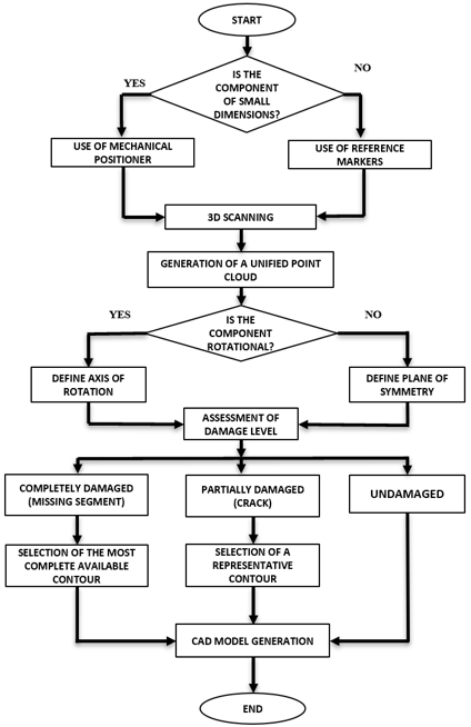
Fig. 1. Algorithm-based model for digital reconstruction of rotational mechanical components
The proposed model is based on the integration of 3D scanning and reverse engineering procedures and is adapted to different preservation states of the investigated component. It consists of a sequence of structured steps and decision-making stages that enable the selection of an appropriate reconstruction strategy depending on component dimensions, symmetry characteristics, and damage level.
The digital reconstruction procedure begins with the 3D scanning phase of the physical object. Depending on the component dimensions, an appropriate positioning method is applied during scanning. For small-sized components, a mechanical positioning device is used, whereas for larger components, scanning is performed using reference markers to ensure reliable alignment of individual scans. After digitization, individual scans are merged into a single unified point cloud, which serves as the primary input dataset for further processing.
In the subsequent stage, an analysis of the component’s geometric characteristics is conducted to determine whether rotational or planar symmetry is present. If symmetry is identified, the corresponding reference element is defined—an axis of symmetry for rotational components or a plane of symmetry for planar geometries. This step enables more efficient utilization of the available scanned data during the reconstruction process.
Following the definition of reference elements, an assessment of the component’s damage level is performed. Based on this evaluation, the component is classified into one of three categories: a partially damaged component with visible cracks, a completely damaged component with one or more missing geometric segments, or an undamaged component. This classification represents a critical phase of the proposed model, as it directly determines the contour selection strategy and the overall reconstruction approach.
- For partially damaged components, a representative contour is selected within a non-deformed region, while missing or damaged segments are reconstructed using symmetry principles and preserved geometric features.
- For completely damaged components, where one or more segments are missing, reconstruction is based on selecting the most complete available contour and supplementing it through symmetry-based operations and local geometric reconstruction.
- For undamaged components, reconstruction relies on the direct use of complete contour lines extracted from the point cloud, enabling CAD model generation without additional geometric corrections.
Based on the defined contours, a complete CAD model of the investigated component is generated, thereby concluding the reconstruction process. The proposed model provides a systematic, repeatable, and adaptable framework for reconstructing mechanical components with varying degrees of damage, supported by clearly defined procedural steps and decision-making criteria.
2.2 3D scanning procedure
Components characterized by sensitive or structurally weak configurations are particularly suitable for non-contact inspection using 3D scanning technologies, while geometric irregularities in complex shapes can be detected more reliably compared to conventional measurement methods [15]. The scanned component represents an articulated mechanical element of the load-bearing structure of a 3D scanner, which experienced fracture during operation. The investigated 3D scanner is supported by three legs, each composed of multiple interconnected articulated elements that enable positional adjustment and structural stability during operation. During service life, one of these articulated elements was damaged, resulting in the need for its reconstruction. The partially damaged component exhibiting visible cracks is shown in Fig. 2a, whereas Fig. 2b presents the completely damaged component with a missing geometric segment. The damage to the investigated component is clearly observable in both cases.
The component was selected as a representative case study due to its pronounced axis of symmetry, the presence of functional surfaces, and the limited accessibility of certain characteristic dimensions for direct measurement, which renders conventional reconstruction methods more demanding. These characteristics make the component suitable for evaluating the application of 3D scanning and reverse engineering in reconstructing parts with varying degrees of damage, as well as for comparison with approaches based exclusively on manual measurement and CAD modeling.
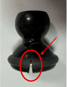
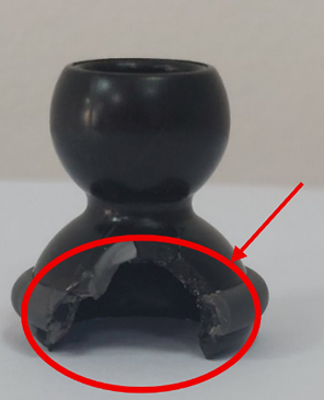
Fig. 2. Articulated mechanical element of the 3D scanner load-bearing structure: (a) fractured component and (b) component with a missing segment due to complete fracture
The geometry of the investigated component was digitized using a RangeVision Smart optical 3D scanner, with a declared accuracy of up to 0.1 mm and a maximum scanning resolution of 0.12 mm, enabling precise acquisition of geometric data required for reverse engineering procedures. The scanner operates based on structured monochromatic light technology for capturing spatial surface coordinates. In order to ensure complete surface coverage and full geometric definition, a rotary positioning table was employed during the experiment. The fundamental object parameters were defined by its geometric dimensions along the x, y, and z coordinate axes [16].
Prior to scanning, the component surface was cleaned and coated with a matte spray (AESUB Clear Self-Volatilizing) to ensure uniform diffuse reflection [17]. This preparation step was necessary due to the black color of the component, as dark and reflective surfaces may lead to data loss and noise generation within the point cloud. The application of a matte layer significantly improves the stability and precision of scanned data acquisition [1].
The measurement setup is illustrated in Fig. 3 and consists of:
1. optical 3D scanner,
2. computer system with data acquisition and processing software,
3. reference markers,
4. investigated component, and
5. rotary positioning table.
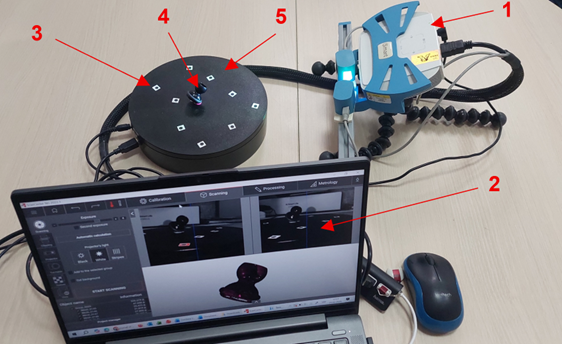
Fig. 3. Measurement setup
Reference markers were placed on the rotary table to ensure more stable alignment and accurate merging of individual scans, thereby improving the quality of object digitization.
Scanning was performed from six different positions using high-resolution acquisition, enabling a higher density of measurement points and a more detailed representation of object geometry [18]. Maximum illumination intensity was applied, and 18 scans were captured per single rotation of the rotary table. The total time required for the scanning process was approximately 20 minutes, including data acquisition and initial processing. Particular emphasis was placed on acquiring a high density of measurement points, as point cloud density directly influences dimensional accuracy and the quality of the reconstructed CAD model.
Although reference markers can facilitate scan alignment, reliable detection requires the scanner to identify at least four markers per scanning position. Due to the small dimensions and symmetrical geometry of the investigated component, marker placement was not suitable. Therefore, auxiliary positioning elements (elastic supports) were applied to selected regions of the object to enable proper alignment during post-processing. After alignment and merging, a unified point cloud containing 2,106,186 points was generated, providing sufficient data density for subsequent segmentation and CAD model generation.
The scanned component in the form of a point cloud is presented in Fig. 4a after merging individual scans and was used as the primary input dataset for geometric reconstruction. The generated mesh model obtained after point cloud processing is shown in Fig. 4b, where a higher model resolution was applied, with activated options for removing small components and scan edge artifacts, while the hole-filling option was intentionally disabled. The threshold of 500,000 vertices was selected based on the default optimization settings implemented in the ScanCenter NG software, which are commonly applied in industrial practice to achieve an optimal compromise between geometric accuracy, processing speed, memory consumption, and system stability. This level of mesh simplification preserves sufficient geometric detail for accurate reconstruction while avoiding unnecessary computational load during further CAD processing and deviation analysis.
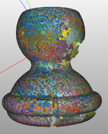
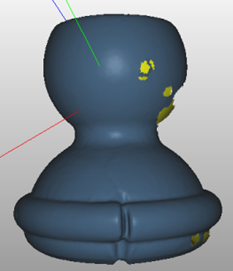
Fig. 4. (a) Point cloud obtained by 3D scanning; (b) generated mesh model after point cloud processing
In addition to the partially damaged component, 3D scanning was also performed on the component with a missing segment due to complete fracture, in order to analyze the influence of damage level on scanned data quality and the subsequent reconstruction process. The point cloud of the completely damaged component is shown in Fig. 5a, while Fig. 5b presents the corresponding mesh model obtained after data processing. The missing geometric segment is clearly visible, representing a characteristic case for application of the proposed digital reconstruction model. After alignment and merging of individual scans, the unified point cloud of the completely damaged component contained 3,335,471 points, indicating high data density and providing a reliable basis for further geometric reconstruction. The higher number of points compared to the partially damaged component results from the increased accessible surface area exposed after fracture.
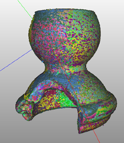
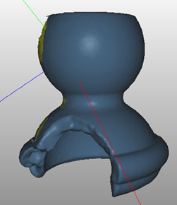
Fig. 5. Completely damaged articulated component: (a) point cloud obtained by 3D scanning; (b) generated mesh model prior to geometric reconstruction
In addition to the damaged components, the original undamaged component was scanned to obtain a reference point cloud and the corresponding CAD model for validation purposes. The point cloud of the undamaged component is shown in Fig. 6a, generated after alignment and merging of individual scans, containing a total of 3,574,415 points, thereby ensuring high data density and accurate digital representation of object geometry. The generated mesh based on the point cloud is presented in Fig. 6b, which served as input data for subsequent geometric reconstruction and analysis within the reverse engineering workflow.
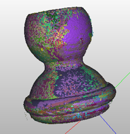
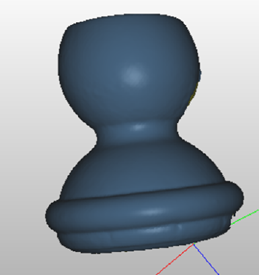
Fig. 6. Undamaged articulated component: (a) point cloud obtained by 3D scanning; (b) generated mesh model prior to geometric reconstruction
2.3 Point cloud processing and CAD model development
Following completion of the 3D scanning procedure and initial data processing in ScanCenter NG 2022.1 software, the scanned models were exported in STL format and imported into Geomagic Design X, which was used for subsequent geometric reconstruction through reverse engineering procedures. The accuracy of the reconstructed CAD model largely depends on the proper selection of reference geometric elements during the modeling process [8]. Geomagic Design X enables advanced point cloud processing and modeling of scanned data, with high compatibility with standard CAD software packages [19]. Since STL models obtained through 3D scanning represent discretized geometry in the form of a triangular mesh, mesh quality and element distribution significantly influence the accuracy of subsequent modeling operations [20]. Therefore, particular attention was devoted to selecting reference surfaces that were not affected by deformation or damage. Following the selection of reference surfaces, the symmetry axis was identified through a two-step procedure. First, geometrically preserved and undamaged reference regions were manually selected on the scanned mesh, such as cylindrical or planar surfaces that had not been affected by cracks, deformation, or missing segments. This step defined the reliable portion of the point cloud/mesh used for axis determination. Second, Geomagic Design X calculated the rotation axis by fitting an appropriate geometric primitive, such as a cylinder, to the selected reference regions using a best-fit procedure. This procedure minimized the overall deviation between the selected mesh data and the corresponding ideal symmetrical geometry, without requiring direct mathematical input from the user.
Since damaged, incomplete, or noisy regions were excluded from the reference selection, the calculated axis was based only on stable and functionally relevant geometry. Once the axis of rotation was defined, the subsequent reconstruction steps, including sectional profile extraction, Mirror operation, and Revolve operation, were performed according to this geometric constraint. Therefore, although the initial selection of reference regions relied on engineering judgment, the core reconstruction process was repeatable, software-driven, and based on defined geometric operations. This justifies the use of the term “algorithmic model” and differentiates the proposed approach from standard manual CAD repair or subjective surface patching.
The investigated component exhibits a well-defined axis of symmetry; therefore, the first reconstruction step involved defining the axis of rotation as the primary reference element. This procedure was applied identically to all three investigated cases: the partially damaged component with preserved geometry, the completely damaged component with a missing segment, and the undamaged component. The axis of rotation was determined based on geometrically preserved and symmetrical regions of the component that were not affected by deformation or damage (regions highlighted in yellow and green in Fig. 7), ensuring reliable applicability regardless of damage level. For the undamaged component, the axis of rotation was defined using fully preserved symmetrical surfaces and subsequently used as a reference axis for comparison with the reconstructed models of the damaged components. The position of the defined rotational axis relative to the scanned models of all investigated cases is shown in Fig. 7.
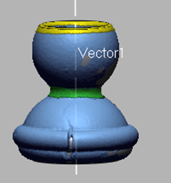
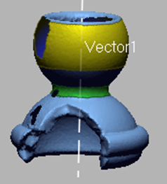
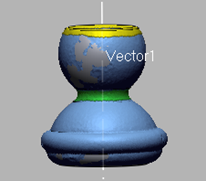
Fig. 7. Axis of rotation: (a) partially damaged component with cracks; (b) completely damaged component with a missing geometric segment; (c) undamaged component
After defining the rotational axis, a sectional plane passing through this axis was constructed. The plane position was carefully selected in a region opposite the damage zone, i.e., within an area unaffected by local geometric deformation. This selection ensured the extraction of a representative cross-sectional profile that accurately describes the original geometry of the component. By intersecting the point cloud with the defined plane, sectional contours were generated for all investigated cases. The cross-section of the partially damaged (cracked) component is shown in Fig. 8a, the cross-section of the completely damaged component with a missing segment in Fig. 8b, and the cross-section of the undamaged reference component in Fig. 8c. These extracted contours were used as input geometry for subsequent parametric CAD model generation.
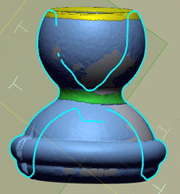
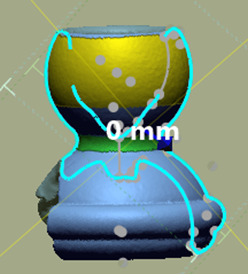
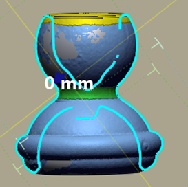
Fig. 8. Sectional plane and contour lines for: (a) partially damaged component with cracks; (b) completely damaged component with a missing geometric segment; (c) undamaged component
For the partially damaged component, the obtained sectional contour was largely derived from the scanned data. However, due to localized irregularities in the external region caused by damage, additional contour correction was required. The geometrically preserved outer region of the cross-section (as visible in Fig. 8a) was used as reference geometry. Based on this preserved portion, the symmetric half of the profile was reconstructed using the Mirror operation, resulting in a complete and closed contour suitable for 3D CAD model generation.
For the completely damaged component with a missing segment, it was observed that the majority of external and internal surfaces were successfully captured during scanning, resulting in a higher number of point cloud elements and more accurately defined sectional contour lines, as shown in Fig. 8b. The external and internal contour lines were sufficient for generating the cross-sectional profile required for 3D model development. Although the geometry of the upper internal region could not be fully captured during scanning, this portion is not functionally critical. Furthermore, since the sectional plane passes through the axis of symmetry, the corresponding missing geometric portion could be reliably reconstructed from the opposite side, ensuring a complete and geometrically consistent cross-section suitable for application of the REVOLVE operation.
In this manner, consistent and equivalent input geometry for CAD model generation was ensured for both damaged cases. Based on the defined contour, the REVOLVE operation was applied to generate the complete 3D CAD model by rotating the sectional profile around the previously defined axis of symmetry. This approach enabled precise geometric reconstruction while reducing modeling complexity and allowing efficient control of key dimensions and functional surfaces.
The application of the REVOLVE operation is illustrated in Fig. 9a, while the final 3D CAD model generated in Geomagic Design X is presented in Fig. 9b.
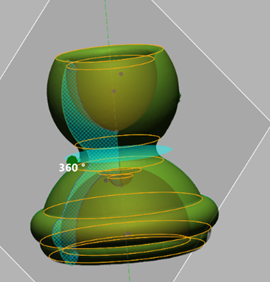
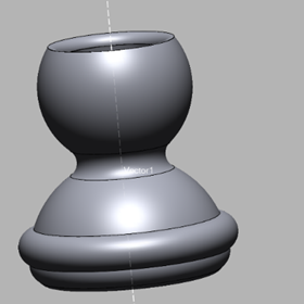
Fig. 9. (a) Application of the REVOLVE operation; (b) reconstructed 3D CAD model
3 Results and discussion
The results analysis includes validation of the developed algorithm-based digital reconstruction model through assessment of the accuracy of the reconstructed CAD models and evaluation of its applicability under different damage conditions.
The application of 3D scanning combined with reverse engineering procedures enabled successful reconstruction of the articulated mechanical element of the 3D scanner load-bearing structure, both in the case of partial damage in the form of cracking and in the case of complete fracture with a missing geometric segment. By utilizing the axis of symmetry of the investigated component and applying the REVOLVE operation in Geomagic Design X, parametric CAD models were generated in both cases, accurately representing the geometry of the original component.
For the partially damaged component, the reconstructed geometry was predominantly based directly on scanned data, with localized contour corrections applied in the external region affected by cracking. In contrast, for the completely damaged component with a missing geometric segment, the algorithmic approach based on local reconstruction and geometric symmetry enabled reliable definition of the missing geometry despite the absence of complete scanned data. The obtained results confirm that the developed model provides a systematic, repeatable, and adaptable reconstruction framework independent of damage level, thereby demonstrating its methodological validity rather than merely successful reconstruction of an individual component.
For quantitative and qualitative evaluation of reconstruction accuracy, the reconstructed CAD models were compared with their corresponding reference point clouds obtained by 3D scanning. The analysis was performed in Geomagic Design X using the geometry comparison function, where deviations between the CAD model and scanned data were visualized as color maps within a predefined tolerance range.
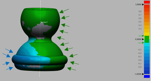
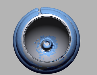
Fig. 10. (a) Deviation map between the CAD model and point cloud of the cracked component; (b) cross-sectional visual comparison of the CAD model and point cloud
The comparison results are presented in Fig. 10, where Fig. 10a shows the deviation color map and Fig. 10b presents a cross-sectional comparison. Minimal deviations, indicated in green, dominate the majority of the model surface, demonstrating strong agreement between the reconstructed geometry and the reference scanned data. These regions of highest geometric conformity are additionally highlighted with green arrows in Fig. 10a. Maximum negative deviations, displayed in light blue shades, are primarily localized in the lower region of the model.
The cross-sectional comparison shown in Fig. 10b confirms the quantitative results, with clear geometric correspondence between the reconstructed CAD model (gray) and the point cloud (blue) across most of the geometry. Local deviations are mainly observed in the damage zone, which is expected due to the presence of cracks and inherent limitations of the scanning process in these regions. The dominant surface deviations remained close to ±0.1 mm, while larger local deviations were primarily associated with geometrically unstable regions affected by cracking and material deformation. A similar distribution and magnitude of deviations were observed for the completely damaged component, confirming the stability and repeatability of the proposed model regardless of the preservation state of the original geometry (Fig. 11).
Observed local deviations can be associated with geometric characteristics of the component and inherent limitations of optical 3D scanning, such as shadowing effects, structured light projection angle, and non-uniform point distribution in certain regions. Shadowing effects occur when recesses, undercuts, sharp transitions, or internal surfaces are occluded by the component geometry, resulting in gaps, incomplete contours, or noisy data in the point cloud. To compensate for such missing or unreliable regions, the proposed model applies a symmetry-based reconstruction strategy instead of conventional manual surface patching. The axis of rotation is defined from stable and geometrically preserved symmetrical regions, while the sectional plane is positioned in a fully visible and undamaged zone, preferably opposite to the shadowed or damaged area. This enables the extraction of a reliable cross-sectional profile. Missing portions of the profile are then reconstructed using the Mirror operation, and the complete 3D geometry is generated using the Revolve operation around the defined axis of symmetry. In this way, missing or occluded regions are reconstructed based on the inherent rotational symmetry of the component, rather than by subjective local approximation. Compared with manual surface patching, the proposed approach improves geometric continuity, repeatability, and reduces operator-dependent error. The stability of the reconstruction strategy is additionally confirmed through statistical deviation analysis, while dominant surface deviations remained confined within a narrow tolerance range close to ±0.1 mm. Although the initial selection of reference regions and the definition of the symmetry axis still require engineering judgment, the proposed algorithmic framework significantly reduces subjectivity compared with conventional reverse engineering procedures.
In addition to these technical factors, reconstruction accuracy may also be influenced by initial user-dependent decisions, particularly during selection of reference regions, definition of the symmetry axis, and positioning of sectional planes. Although the developed model is structured and repeatable, these initial steps rely on engineering judgment and may introduce minor variability.
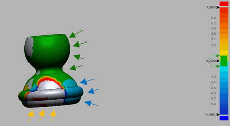
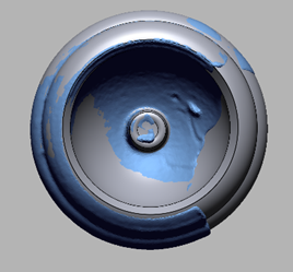
Fig. 11. (a) Deviation map between the CAD model and point cloud of the completely fractured component; (b) cross-sectional visual comparison
The deviation color map in Fig. 11a shows that minimal deviations (green zones) dominate the surface area. Maximum negative deviations (blue shades) are localized in the lower region of the model, whereas larger positive deviations are observed in regions reconstructed using symmetry operations. The reconstructed segment corresponding to the originally missing portion is highlighted in Fig. 11a (yellow arrow). This segment is continuously and seamlessly integrated with the remaining geometry, without pronounced discontinuities in transitional zones. The observed deviations are primarily localized in non-critical functional regions that were either damaged or reconstructed using symmetry constraints, confirming the validity of the selected reference regions and sectional planes, as well as the correct implementation of geometric symmetry as a modeling constraint.
The cross-sectional comparison in Fig. 11b further confirms strong geometric agreement across most of the component volume. Despite the absence of the original segment, the reconstructed geometry exhibits continuity and consistency with the existing scanned data, demonstrating the reliability of the applied reconstruction model. From a practical standpoint, the results indicate that the proposed model enables rapid and reliable generation of functional replacement components even when the original geometry is not fully preserved.
The statistical deviation analysis was performed based on characteristic dimensional measurements extracted from reconstructed CAD models and their corresponding reference scanned geometries obtained by optical 3D scanning.
Table 1. Statistical deviation analysis of reconstructed components
|
Component state |
Mean deviation (mm) |
Standard deviation (mm) |
RMSE (mm) |
|
Partially damaged component (D2) |
0.0219 |
0.1106 |
0.1065 |
|
Completely damaged component (D3) |
0.0370 |
0.0662 |
0.0661 |
In addition to qualitative deviation color-map analysis, statistical deviation metrics were calculated based on characteristic dimensional measurements extracted from reconstructed CAD models and reference geometry. Mean deviation, standard deviation, and RMSE values were determined for both damaged cases in order to quantitatively evaluate reconstruction stability and repeatability. The obtained statistical results confirmed that the proposed reconstruction strategy provides consistent geometric reconstruction with limited dimensional variability. Slightly higher deviation values observed for the partially damaged component (D2) are associated with local geometric deformation caused by crack propagation and dimensional instability in the damaged region prior to scanning.
For complete validation, the reconstructed CAD model was additionally compared with the point cloud obtained from 3D scanning of the undamaged reference component. The visual and color-map comparison for the undamaged case is presented in Fig. 12. Deviations between the CAD model and the point cloud are minimal and uniformly distributed, with dominant values close to zero deviation (green zone). This result confirms the high accuracy of both the 3D scanning process and the reconstruction procedure in the case of fully preserved original geometry, and validates the CAD model used as a reference for analysis of partially and completely damaged components.
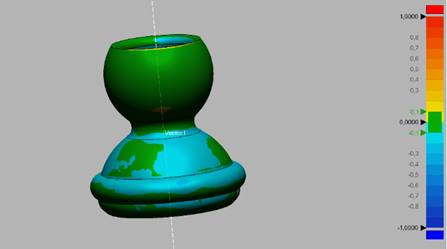
Fig. 12. Comparison between the reconstructed CAD model and the point cloud of the undamaged component
Compared to conventional approaches based exclusively on manual measurement and traditional CAD modeling, the applied model integrating 3D scanning and reverse engineering significantly reduces reconstruction time while increasing repeatability and accuracy. A major advantage of this approach lies in the direct digitalization of complex geometries and generation of CAD models based on real geometric data, thereby minimizing subjective errors characteristic of manual modeling.
The results demonstrate that the application of 3D scanning combined with reverse engineering represents an efficient and reliable method for reconstruction of small symmetrical mechanical components, both in cases of partial damage (cracking) and complete fracture with missing segments. Comparative analysis of reconstructed CAD models with reference point clouds showed that dominant surface deviations in both damaged cases remained within a narrow tolerance range, while statistical deviation analysis confirmed good reconstruction repeatability and dimensional consistency. Additional comparison with the undamaged reference point cloud enabled comprehensive validation of the applied procedure, confirming that the defined reference elements, symmetry axes, and sectional planes ensure consistent and repeatable geometric reconstruction independent of the preservation state of the original component. This confirms that the proposed model enables reliable reconstruction of original geometry even when the reference component is not fully preserved.
The analysis further indicates that while 3D scanning and reverse engineering require increased effort during the digitization and initial geometric data processing phases, they simultaneously enable a high degree of automation in CAD model generation and reliable dimensional accuracy control for rotational and geometrically complex components. This approach is particularly advantageous when certain characteristic dimensions are difficult to access for direct measurement or when consistent and repeatable reconstruction is required with minimal risk of subjective modeling errors.
The total time required for digitization of the investigated component using 3D scanning was approximately 20 minutes, while point cloud processing and CAD reconstruction required an additional 15 minutes. The obtained results indicate that the proposed model enables relatively rapid and efficient geometric reconstruction while maintaining high dimensional accuracy. Nevertheless, reconstruction precision strongly depends on the quality of the initial digitization and the proper selection of reference regions during point cloud processing.
4 Conclusions
The development of modern digital technologies, particularly non-contact 3D scanning, has significantly advanced the reconstruction and analysis of existing mechanical components. Compared to conventional measurement methods, digital approaches based on 3D scanning enable faster and more comprehensive geometry digitization, more reliable identification of complex shapes, and a reduction in subjective modeling errors.
This study presented an algorithm-based model for digital reconstruction of a rotational mechanical component founded on the integration of 3D scanning and reverse engineering techniques. The proposed approach considers different preservation states of the physical component, including an undamaged part, a partially damaged part with cracking, and a completely damaged part with missing geometric segments, thereby ensuring broad applicability under real industrial maintenance and repair conditions.
The implementation of the symmetry axis as the primary geometric constraint enabled reliable reconstruction even in cases where scanned data were incomplete. Comparative analysis between reconstructed CAD models and reference point clouds demonstrated that dominant surface deviations remained within a narrow tolerance range close to ±0.1 mm. Additional statistical deviation analysis confirmed the stability, repeatability, and dimensional consistency of the proposed reconstruction methodology. This level of accuracy confirms that the proposed methodology enables faithful and reliable reconstruction of the original geometry regardless of the preservation state of the component.
In comparison with conventional approaches based solely on manual measurement and traditional CAD modeling, the proposed model reduces the risk of subjective errors, enhances process repeatability, and enables efficient reconstruction of geometrically complex components and dimensions that are difficult to access directly. The obtained results indicate that the proposed framework represents an efficient and reliable solution for digital reconstruction of small symmetrical mechanical components, particularly in situations where original technical documentation is unavailable or the component is partially or completely damaged.
Future research may focus on extending the applicability of the model to components lacking pronounced geometric symmetry, as well as on integrating additional quantitative accuracy metrics, automated criteria for reference region selection, and automated statistical deviation extraction directly from point cloud comparison software for complex geometries.
Acknowledgements
The authors gratefully acknowledge the Academy of Applied Technical and Preschool Studies, Niš, and the Laboratory of Advanced Technologies for their continuous institutional support and for providing the technical and laboratory resources essential for this research.
References
- Helle, R. H., & Lemu, H. G. (2021). A case study on use of 3D scanning for reverse engineering and quality control. Materials Today: Proceedings. https://doi.org/10.1016/j.matpr.2021.01.828
- Haleem, A., Gupta, P., Bahl, S., Javaid, M., & Kumar, L. (2020). 3D scanning of a carburetor body using COMET 3D scanner supported by COLIN 3D software: Issues and solutions. Materials Today: Proceedings. https://doi.org/10.1016/j.matpr.2020.07.427
- Peiravi, A., & Taabbodi, B. (2010). A reliable 3D laser triangulation-based scanner with a new simple but accurate procedure for finding scanner parameters. Journal of American Science, 6(5), 80–85.
- Kunytsia, A., & Lashyna, Y. (2025). Comparison and evaluation of conventional and machine learning-assisted reverse engineering workflows. Mechanics and Advanced Technologies, 9(3), 298–308. https://doi.org/10.20535/2521-1943.2025.9.3(106).333347
- Bansal, M., & Dhami, S. S. (2017). 3D scanning for reverse engineering – Technological advancements, process overview, accuracy inspection, challenges and remedies. International Journal of Emerging Technologies in Engineering Research, 5(10), 33–40.
- Raja, V., & Fernandes, K. J. (Eds.). (2008). Reverse engineering: An industrial perspective. Springer-Verlag London.
- Emzain, Z. F., Mufarrih, A. M., Hartono, M., Qosim, N., & Herlambang, Y. D. (2024). Reverse engineering modeling processing and fabrication of Voronoi perforated ankle-foot orthosis. Journal of Applied Engineering Science, 22(3), 573–582. https://doi.org/10.5937/jaes0-48262
- Bushra, J., Rahman, M. H., Shafae, M., & Budinoff, H. D. (2024). Distortion minimization in reverse engineering for additive manufacturing: An integrated 3D scanning and simulation framework. Journal of Manufacturing Technology Management. https://doi.org/10.1108/JMTM-10-2023-0471
- Debnath, B., Pourfarash, Z., Ghorpade, B., & Raman, S. (2025). Integrating reverse engineering for digital model reconstruction and remanufacturing of mechanical components: A systematic review. Metrology, 5, 66. https://doi.org/10.3390/metrology5040066
- Corzanu, V., Duta, A., Corzanu, A., & Popa, D.-L. (2025). Integration of 3D scanning technologies in the design of surfaces obtained by tessellations. Acta Technica Napocensis, Series: Applied Mathematics, Mechanics, and Engineering, 68(2), 471–476.
- Antova, G., & Tanev, V. (2020). Creation of 3D geometry in Scan-to-CAD/BIM environment. IOP Conference Series: Earth and Environmental Science, 609(1), 012085. https://doi.org/10.1088/1755-1315/609/1/012085
- Klimecka-Tatar, D., & Krynke, M. (2025). Reverse engineering tools – 3D scanning – as support for precise quality control in automated special processes. Procedia Computer Science, 253, 1933–1942. https://doi.org/10.1016/j.procs.2025.01.255
- Riyadi, T. W. B., Yulianto, Y. H., Effendy, M., Sarjito, Zheng, Z., & Tang, L. P. (2018). Evaluation on a digitized CAD model of 3D scanner used in reverse engineering. In Proceedings of the 12th South East Asian Technical University Consortium Symposium (SEATUC 2018) (pp. 1–5). IEEE. https://doi.org/10.1109/SEATUC.2018.8788885
- Soković, M., Cedilnik, M., & Kopač, J. (2005). Use of 3D-scanning and reverse engineering by manufacturing of complex shapes. In Proceedings of the 13th International Scientific Conference on Achievements in Mechanical and Materials Engineering (AMME 2005) (pp. 601–604).
- Chaudhary, K., & Govil, A. (2022). Application of 3D scanning for reverse manufacturing and inspection of mechanical components. In R. P. Singh et al. (Eds.), Proceedings of the International Conference on Industrial and Manufacturing Systems (CIMS-2020) (pp. 69–84). Springer Nature Switzerland AG. https://doi.org/10.1007/978-3-030-73495-4_5
- Veretekhina, S. V. (2020). Digitization, scanning, and reverse engineering technology for creating 3D virtual space. Journal of Physics: Conference Series, 1679(2), 022085. https://doi.org/10.1088/1742-6596/1679/2/022085
- Zhang, L., Xiong, C., & Tang, J. (2025). Research on curved surface reconstruction based on Geomagic Design X. In M. Penza & S. Wang (Eds.), Proceedings of SPIE – Third International Conference on Advanced Materials and Equipment Manufacturing (AMEM 2024), 13691, 136911D. SPIE. https://doi.org/10.1117/12.3068702
- Ali, F., Chowdary, B. V., & Imbert, C. A. C. (2008). Part design and evaluation through reverse engineering approach. In Proceedings of the IAJC-IJME International Conference (Paper #54, ENG 103).
- Yin, H., Ding, Y., Long, C., Wang, L., Jiang, Z., Wang, Z., Zhang, J., Yang, Y., Wu, G., & Li, X. (2025). Hybrid modeling and rapid prototyping technology based on the Geomagic system. Scientific Reports, 15, 42456. https://doi.org/10.1038/s41598-025-26566-0
- Deng, Z., Xiong, W., & Ge, Y. (2026). STL model optimization and point cloud registration method for posture measurement of mechanical parts. In B. Dong & Y. Chen (Eds.), Proceedings of SPIE – Fifth International Conference on Advanced Manufacturing Technology and Electronic Information (AMTEI 2025), 14066, 140661M. https://doi.org/10.1117/12.3096115
Conflict of Interest Statement
The authors declare that there is no conflict of interest regarding the publication of this paper.
Author Contributions
Data Availability Statement
The datasets generated and analyzed during the current study are not publicly available due to their size and format but are available from the corresponding author upon reasonable request.
Supplementary Materials
There are no supplementary materials to include.