Volume 23 article 1301 pages: 656-663
Received: Dec 27, 2024 Accepted: Aug 04, 2025 Available Online: Nov 10, 2025 Published: Dec 15, 2025
DOI: 10.5937/jaes0-55707
ANALYSIS OF THE IMPACT OF INSTALLING CAI AND IMS ON A MOTORCYCLE ENGINE
Abstract
Engine performance and fuel efficiency are very important in a motor vehicle, so many studies aim to improve the performance of motor vehicles. The Intake Manifold Spacer (IMS) is placed on the intake manifold channel before the air and fuel mixture enters the combustion chamber, while the Cyclonic Air Injector (CAI) is placed on the air channel that will enter the carburettor chamber. With the addition of IMS and CAI, it is expected to increase the homogeneity of the fuel-air mixture and provide a turbulent flow effect (swirling) on the air entering the carburettor and the air-fuel mixture entering the combustion chamber. The method used in this study is to manufacture IMS and CAI with variations in the number of blades: 3 and 4 and the angle of inclination of the blades 35o and 45o. Testing was conducted on a 110cc 4-stroke motorcycle, where a dyno test was used to determine power, torque, and fuel consumption. The results of this study show that the addition of IMS and CAI can improve performance and increase fuel efficiency compared to standard motor vehicle conditions. The largest increase in motor power was in the variation of adding IMS and CAI with 4 blades and a blade angle of 35o, which was 3.9%. Meanwhile, the maximum torque increased by 3.9 in the variation of adding IMS and CAI with 4 blades and a blade angle of 45o. Fuel consumption also experienced savings or decreased compared to the standard conditions of all test variations. The highest efficiency of 9.36% occurred in the variation of adding IMS. Based on this research, it can be one of the considerations to improve the performance of combustion engines for the automotive industry. It can also serve as a reference for other researchers who wish to conduct research on combustion engine performance.
Highlights
- Developed and tested IMS and CAI devices on a 110cc 4-stroke motorcycle.
- Blade numbers (3 and 4) and angles (35° and 45°) significantly influenced airflow dynamics.
- The combined IMS and CAI setup improved engine power by up to 3.9%.
- Maximum torque increased by 3.88% with a 4-blade, 45° CAI configuration.
- Fuel consumption decreased by up to 15.47%, indicating higher fuel efficiency.
Nomenclature
Symbol/Term Description
IMS Intake Manifold Spacer
CAI Cyclonic Air Injector
RPM Revolutions Per Minute
HP Horsepower
Nm Newton-meter
SFC Specific Fuel Consumption (kg/hour.HP)
b Volume of fuel used in a test (l)
ρbb Fuel density (kg/l)
mbb Fuel consumption mass (kg/hour)
T Torque (kg·m)
P Engine power output (HP)
n Engine shaft rotation (RPM)
Keywords
Content
1 Introduction
Motorcycles are one of the most popular vehicles for the community due to their efficiency and relatively low prices. Along with the increasing demand for motorcycles, many companies are competing to increase the level of motorcycle specifications to attract consumers to buy their products. Fuel efficiency and good engine performance are still the most important factors for a motorcycle.
Installing a turbocyclone can be a solution to overcome fuel consumption and improve efficiency with good engine performance, as it creates a swirling or rotating air flow entering the carburetor and combustion chamber [1,2]. According to the simulation, the design and application of turbocyclones and manifold spacers can significantly improve the performance of small-capacity motorcycles, potentially leading to better fuel efficiency and reduced emissions [3,4]. Optimizing the swirl ratio in a compression ignition engine is crucial for achieving better engine performance, including improved combustion efficiency and reduced emissions [7]. Complete combustion can improve engine performance and fuel efficiency [8]. One of the conditions for complete combustion is a homogeneous fuel-air mixture entering the combustion chamber [9,10]. The study about modification of intake manifold [11,12] indicates that commercial codes can be used to investigate different configurations of internal combustion engines' intake manifolds, and that simple modifications to the manifold geometry can lead to significant improvements in engine performance [13,14].
The research about the influence of the number of blades on the turbocyclone shows that the 4-blade turbo cyclone and IMS are the most effective variations for increasing the torque and power of the 100cc motorcycle, indicating that the number of blades in the turbo cyclone influences the engine's performance [15,16]. A curved diffuser helps increase static pressure by reducing gas lift and flow resistance. The pressure shape becomes concave, influenced by both suction and driving fluid pressures [17].
Therefore, research on the effect of adding equipment that causes the airflow entering the carburetor to rotate or the mixture of fuel and air that will enter the combustion chamber to be more homogeneous is still needed. Furthermore, research that applies to a cyclonic air injector (CAI) and intake manifold spacer (IMS) with variations in the number of blades and variations in the angle of inclination of the blades is expected to improve the performance and fuel efficiency of 4-stroke motor vehicles.
The novelty of this research is the combined installation of the Intake Manifold Spacer (IMS) and the Cyclonic Air Injector (CAI) with variations in blade number (3 and 4) and angle (35° and 45°) to create optimal turbulence and improve the homogeneity of the air-fuel mixture, resulting in increased power, torque, and fuel efficiency in a 110cc motorcycle engine.
2 Materials and methods
This research methodology is divided into three stages: modeling, manufacturing, and testing. In the modeling stage, (CAI) and (IMS) are developed. CAI is created with variations in blade angles, such as 35o and 45o, with 3 or 4 blades. Similarly, IMS modeling involves the design of 24 grooves to enhance functionality. These grooves can be strategically placed to optimize engine performance and fuel efficiency.
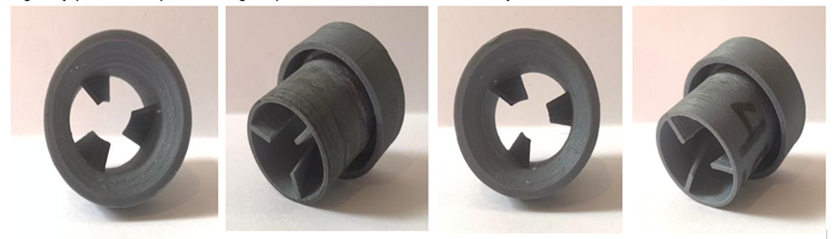
Fig. 1. Design of CAI 3 blades
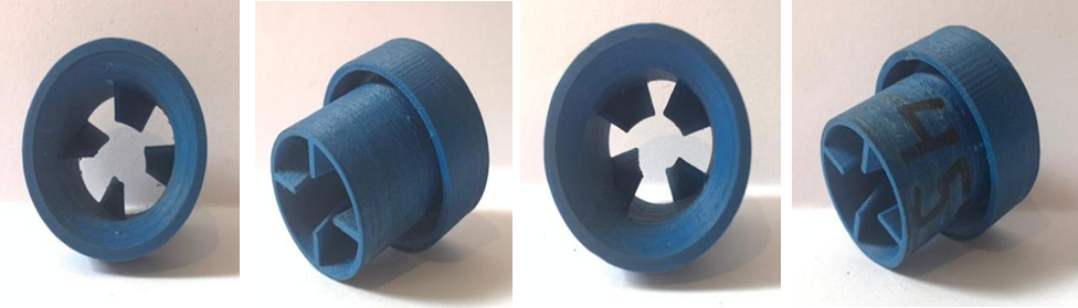
Fig. 2. Design of CAI 4 blades
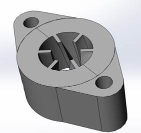
Fig. 3. Design of IMS
The final stage is testing the performance of the motorcycle by using additional CAI and IMS, comparing it to the standard condition. This test measures the power, torque, and fuel consumption by comparing the engine speed (RPM).
Finally, the testing stage evaluates the performance and functionality of the manufactured CAI and IMS systems. Various tests are conducted to ensure the systems meet the desired specifications and operate effectively. Overall, this research methodology encompasses a comprehensive approach to developing and accessing CAI and IMS systems for optimal performance.
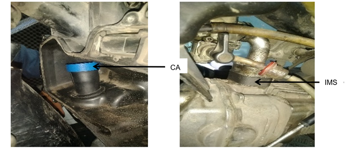
Fig. 4. CAI and IMS installed on the motorcycle
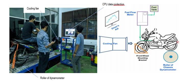
Fig. 5. Setup testing the performance of the motorcycle using dyno test
The motorcycle specifications are: Engine type: 4-stroke, SOHC with Engine Capacity: 109.1cc (110), compression ratio: 9.0:1, maximum power: 8.46 PS (8.34 HP) @7500 RPM and maximum torque: 0.86 kgm (8.43 Nm) @5500 RPM.
Torque (T)
Torque is the rotational force generated when the piston moves downward during the engine's operation, leading to the rotation of the crankshaft via the piston rod. The amount of torque produced increases with the pressure exerted on the piston. Therefore, higher combustion pressure results in more torque. Typically, torque in engines is measured using a dynamometer, which can also measure power simultaneously through the dynamometer equation.
![]() (1)
(1)
Where T is the torque moment of the object (kg.m), P is power (HP) and n is engine shaft rotation (RPM)
Power (P)
Power is the amount of motor work per unit time. Power on a motorbike can be measured using a tool known as a dynamometer, with power units expressed in hp (horsepower)
![]() (2)
(2)
Where P is power (HP), T is torque (kg.m) and n is engine shaft rotation (RPM)
Specific Fuel Consumption (SFC)
Specific fuel consumption is the amount of fuel needed to burn each hour to produce one unit of power. This specific fuel consumption calculation is used to determine the amount of fuel needed to produce power in a certain time. If the power is in kW units and the fuel mass flow rate is in kg/hour then the specific fuel consumption can be formulated:
![]() (3)
(3)
![]() (4)
(4)
Where SFC is specific fuel consumption (kg/hour.HP), mbb is fuel consumption (kg/hour), b is weight volume (MI) t is burette empty time (s) and ρbb is fuel density (kg/l).
3 Result and discussion
Fig. 6. Comparison between power, torque, and engine rotation
As can be seen in Fig. 6 above, according to the test results with 6 test variations, the comparison between power (HP), torque (Nm) and engine speed (RPM). Fig. 4.a shows the basic performance of the engine in its standard configuration. However, the optimal combination of power and torque occurs at engine speeds of 5000-5500 RPM.
As can be seen in Fig. 6.a, the maximum power produced is 7.7 HP at 6250 RPM, and the maximum torque produced is 9.81 Nm at 4,750 RPM. Compared to the specifications issued by the motor vehicle manufacturer, the standard conditions of this test show that the maximum power that can be produced is 8.34 HP at 7500 RPM and the maximum torque is 8.43 Nm at 5500 RPM. This indicates that the condition of the vehicle is still normal and meets the requirements for testing. This indicates that the condition of the vehicle is still normal and meets the requirements for testing. according to Fig. 6.b above, by adding the intake manifold spacer (IMS) reached the maximum power reached 7.8 HP and the maximum torque reached 9.87 Nm. This shows an increase in maximum power of 1.3% and maximum torque of 0.6% compared to standard conditions. Although the results are not significant, the addition of IMS can improve the performance of the motor vehicle.
In the variation of IMS and CAI addition with the number of blades 3 and a blade inclination of 35o as shown in Fig. 6.c, a maximum power of 7.8 HP and a maximum torque of 9.91 Nm were obtained. When compared to standard conditions, there was an increase in power of 1.3% (the same as with only the addition of IMS) while the torque increased by 1.01%. This shows an increase compared to the variation with IMS addition alone. While in the graph on Fig. 6d, where the variation of the addition of IMS and CAI with the number of blades is 3 and the blade angle inclination of 45o, an increase in power of 2.6% and torque of 2.03% was obtained.
As seen in Fig. 6.e, the variation of IMS and CAI addition with the number of blades 4 with a blade inclination of 35o obtained a maximum power increase of 3.9% and the maximum torque also increased by 2.02%, while in the last variation, where the addition of IMS and CAI with the number of blades 4 with a blade inclination of 45o as seen in Fig. 6. if there was an increase in power of 2.6%, while torque experienced a significant increase of 3.8%.
Fig. 7. Comparison of power (HP) generated from various test variations
Fig. 7 shows the relationship between engine speed (RPM) and power (HP) in various test variations, where all test variations show maximum power and maximum torque, followed by a decrease as the engine speed continues to increase. Various configurations involving the addition of IMS + CAI generally produce greater power than the standard condition, and even the addition of IMS alone, especially at mid-range RPM. The number and angle of certain blades affect the power curve, with some variations performing better at specific RPM ranges. This graph concludes that the combination of IMS + CAI generally improves performance over standard conditions, with the best variation depending on the targeted RPM range. The maximum power for each variation occurs near the peak of its respective curve. Visually, it can be seen that the highest power is obtained from the variation of IMS + CAI 3 blades and a blade pitch angle of 45o and IMS + CAI 4 blades 35o, which reaches a maximum power of 8 HP.
Fig. 8. Comparison of Torque (Nm) generated from various test variations
In the graph of Fig. 8 which shows the relationship between engine rotation speed (RPM) and torque (Nm) in various test variations. The main conclusion from the graph is that the addition of IMS and CAI can increase engine torque compared to standard conditions. The highest torque occurs in the addition of IMS + CAI with 4 blades and a 45o tilt angle, with the highest torque of 10.18 Nm.
Fig. 9. Comparison of fuel consumption at various engine speeds and test variations
Fig. 9 shows the average fuel consumption diagrams in kg/h for different engine configurations and RPM. The independent variables are engine configuration (Standard, IMS, IMS+CAI 3 blades 35o, IMS+CAI 3 blades 45o, IMS+CAI 4 blades 35o, and IMS+CAI 3 blades 45o) and engine speed (4000 RPM, 5000 RPM, and 6000 RPM). For all test variations, fuel consumption increases with higher RPM. The standard engine configuration consistently shows the highest fuel consumption at all RPMs. Applying IMS alone reduces fuel consumption compared to the standard engine. Adding CAI further reduces fuel consumption compared to IMS alone. Among the CAI configurations, 3 blades and 35o blade pitch generally show the lowest fuel consumption, especially at 4000 and 5000 RPM. The IMS+CAI test variations showed a significant improvement in fuel efficiency compared to the standard and IMS-only setups. The number of blades and the specific CAI angle affected fuel consumption, with 3 blades and a 35o blade pitch generally performing the best. This suggests that optimizing the CAI design can yield significant fuel savings.
4 Conclusions
Based on the research and analysis that has been done previously about the effect of variations of the CAI and IMS, it can be concluded:
- The addition of IMS and CAI can improve motorcycle performance, with both maximum power and maximum torque increasing, and there is an increase in fuel efficiency across all test variations.
- The largest increase in maximum power occurs in the variation of the addition of IMS and CAI 4 blades with an angle of 35o, which is 3.9% compared to standard conditions.
- The largest increase in maximum torque occurs in the variation of the addition of IMS and CAI 4 blades with an angle of 45o, which is 3.88% compared to standard conditions.
- The largest fuel efficiency improvement is 15.47% in the variation with the addition of IMS.
Acknowledgements
The authors express appreciation and thanks to the Directorate General of Research, Technology, and Higher Education, Ministry of Education and Culture of the Republic of Indonesia, for the scheme of Flagship Regular Fundamental Research (PFR) financial year 2024, with contract number 108/E5/PG.02.00.PL/2024 dated June 11, 2024.
References
- S. Huda, W. Purwanto, and B. U. Wisesa, “The Effect of Turbo Cyclone Installation on 4 Stroke Motor Cycle on Fuel Consumption and Exhaust Emissions,” Motiv. J. Mech. Electr. Ind. Eng., vol. 3, no. 2, pp. 69–76, 2021.
- P. Kumar, A. Darsigunta, B. Chandra Mouli, V. Kumar Sharma, N. Sharma, and A. Singh Yadav, “Analysis of intake swirl in a compression ignition engine at different intake valve lifts,” Mater. Today Proc., vol. 47, no. xxxx, pp. 2869–2874, 2021.
- Sarjito, Sandhika Putra Pratama, Wijianto, and Subroto, “Computational Fluid Dynamic Analysis of Turbo Cyclone and Intake Manifold Spacer on Honda Supra Fit,” JTTM J. Terap. Tek. Mesin, vol. 3, no. 1, pp. 9–18, 2022.
- B. Menacer, “Simulation and Modelling of a Turbocharged Compression Ignition Engine,” Int. J. Energy Power Eng., vol. 4, no. 3, p. 129, 2015.
- A. Palacios, D. Bradley, Q. Wang, X. Li, and L. Hu, “Air/fuel mixing in jet flames,” Proc. Combust. Inst., vol. 38, no. 2, pp. 2759–2766, 2021.
- S. Zhang, M. Shin, and W. G. Shin, “Comparison of models to predict the collection efficiency of an axial cyclone with a spindle vane,” J. Aerosol Sci., vol. 157, no. May, p. 105817, 2021.
- Y. Chen et al., “Effects of intake swirl on the fuel/air mixing and combustion performance in a lateral swirl combustion system for direct injection diesel engines,” Fuel, vol. 286, no. P1, p. 119376, 2021.
- V. N. Duy, K. N. Duc, and N. C. Van, “Real-time driving cycle measurements of fuel consumption and pollutant emissions of a bi-fuel LPG-gasoline motorcycle,” Energy Convers. Manag. X, vol. 12, p. 100135, 2021.
- V. McDonell, Lean combustion in gas turbines. Elsevier Inc., 2016.
- Y. Zhang and H. Zhao, “Investigation of combustion, performance and emission characteristics of 2-stroke and 4-stroke spark ignition and CAI/HCCI operations in a DI gasoline,” Appl. Energy, vol. 130, pp. 244–255, 2014.
- S. P. Pratama, K. A. Ilham, and K. Haryanto, “Performance Analysis Turbo Cyclone and Intake Manifold,” 2023.
- T. Polonec and I. Janoško, “Improving performance parameters of combustion engine for racing purposes,” Res. Agric. Eng., vol. 60, no. 3, pp. 83–91, 2014.
- G. R. de Souza, C. de C. Pellegrini, S. L. Ferreira, F. Soto Pau, and O. Armas, “Study of intake manifolds of an internal combustion engine: A new geometry based on experimental results and numerical simulations,” Therm. Sci. Eng. Prog., vol. 9, pp. 248–258, 2019.
- G. Aji Saputra and S. Putro, “Study Experimental of Honda Astrea Grand Performance Modification Intake Manifold Using Velocity Stack Dimple 1mm with Variation Diameter Inlate 60, 70, and 80mm,” E3S Web Conf., vol. 517, pp. 1–4, 2024.
- Wijianto, Sarjito, Subroto, A. Sulistyanto, and K. Hariyanto, “Experimental Investigation Performance of Motorcycle 100cc With a Variation of Octane Number of Fuel (RON) and Additional Cyclonic Air Injector (CAI),” AIP Conf. Proc., vol. 2838, no. 1, 2024.
- Wijianto, H. W. Rachman, Supriyono, and Muamaroh, “Influence of the Number of Blades in hydro microturbine due to flow velocity,” AIP Conf. Proc., vol. 2114, no. June, 2019.
- M. Effendy, A Salim, T.Syawitri, and D. Sugari, “Performance of liquid-gas ejector with curve diffuser in vertical flow,” Result In Engineering Journal., vol. 25, page(s) 104434, 2025, https://doi.org/10.1016/j.rineng.2025.104434,
Conflict of Interest Statement
The authors declare that there is no conflict of interest regarding the publication of this paper.
Author Contributions
Data Availability Statement
The data that support the findings of this study are available from the corresponding author upon reasonable request.
Supplementary Materials
No supplementary materials are available or provided for this manuscript.