Volume 23 number 3 article 1282 pages 394-404
Received: Apr 26, 2025 Accepted: Aug 04, 2025 Available Online: Aug 23, 2025 Published: Sep 15, 2025
DOI: 10.5937/jaes0-51237
COMPARATIVE ANALYSIS OF POST-TENSIONED FLAT SLAB WITH CONVENTIONAL DESIGN USING BUILDING INFORMATION MODELLING (BIM) INTEGRATION IN TOWER STRUCTURE
Abstract
The tower structure consisted of 13 floors and a roof, with a maximum elevation of 52.4 meters, and was studied in this research. Classified under Seismic Design Category D with a risk factor of IV, it underwent the design process using both conventional methods (CONV) with a dual system (open-frame and special shear wall) system and compared to the post-tensioned flat slab (PTFS) method, integrated with Building Information Modelling (BIM) through ETABS 21 and Revit 2023 software. In the PTFS structural system, seismic forces were resisted by perimeter frames and shear walls. While gravity columns in the PTFS structure did not directly withstand seismic forces, they were designed using the compatibility displacement method. The PTFS structure had a lighter structural mass but greater stiffness than CONV structural system, resulting in decreased story drift and displacement but higher values of story shear and overturning moment. Through analysis and volume cost calculations, the study demonstrated cost savings of $221,118, equivalent to 10.2% of the structural cost, by implementing the post-tensioned flat slab system.
Highlights
- BIM integration enables seamless data exchange between Revit 2023 and ETABS V21 for structural design optimization.
- Post-Tensioned Flat Slab system integrated with dual system improves lateral force resistance in seismic zones.
- Gravity and lateral systems are separated; gravity columns are designed using displacement compatibility for seismic stability.
- Comparative analysis of conventional and PTFS dual systems reveals performance benefits in high seismic hazard zones.
Keywords
Content
1 Introduction
In the Architectural, Engineering, and Construction (AEC) industry, Building Information Modelling (BIM) has the capability to optimize tasks, enhance design creativity, minimize rework, improve work quality, shorten construction periods, reduce overall costs, and enhance interdisciplinary collaboration [1-2]. The utilization of BIM can also prevent clashes and mitigate weak coordination between disciplines [3-4]. The implementation of BIM in structural engineering is anticipated to yield a substantial enhancement in productivity, coordination, data exchange, and the provision of simulations for real-world challenges encountered in the field [5]. However, the utilization of BIM in Indonesia's construction sector remains low compared to other countries in Southeast Asia [6]. This circumstance has hindered Indonesia's potential progress within the construction industry.
The concept of BIM integration here will be implemented in the processes of modelling, analysis, and design of the Tower structure. The BIM integration will be performed using Revit 2023 as the modelling software and ETABS 21 as the structural analysis software. However, it's worth noting that the ETABS model may have a lower effective seismic mass because the program does not calculate the overlapping elements at the joint [7]. The structural model and reinforcement detailing between this software can be integrated directly as the BIM Supported software [5, 8].
This tower structure will be designed using both conventional methods (Special Moment Resisting Frame - SMRF system) and a post-tensioned flat slab system. For typical and symmetrical floors, the post-tensioned flat slab system has the highest economic value compared to other floor systems [9]. Post-tensioned flat slab exhibits lower shear and moment internal forces, thereby reducing the reinforcement requirements for the slab [10]. The advantage of the post-tensioned flat slab system lies in its more economical structural costs, providing greater floor-to-floor distances, ease of construction processes, and lighter structural weight [11].
Post-tensioned flat slab systems with a minimum span of 7 m resulted in savings of 10-20% due to reduced material costs compared to conventional beam and slab systems [12]. Furthermore, employing post-tensioned panels with dimensions of 8 meters by 8 meters has resulted in cost savings of 25-35% compared to conventional slab methods [13-14].
Despite the cost savings and advantages, post-tensioned flat slab systems present a more flexible structural configuration, demanding careful design to avoid surpassing structural drift limits [15-16]. Introducing shear walls can reduce the base shear and enhance the flat slab structure's ability to resist lateral loads [17]. Particularly in regions with significant seismic activity, combining flat slab systems with perimeter frames or shear walls is essential for optimal seismic performance [18].
Moreover, flat slab structures are more vulnerable to collapse during seismic events compared to conventional structures. Under lateral forces induced by earthquakes, punching shear forces exceeding the shear resistance capacity of concrete can lead to punching shear failure. Due to their lower redundancy compared to conventional column-beam structural systems, significant force redistribution occurs in adjacent columns if one column experiences punching shear failure [19]. Therefore, a separation of structural systems between the gravity load-resisting system and the lateral load-resisting system is undertaken. The implementation of this system will result in gravity columns only moving in response to seismic loads without resisting seismic forces. This separation functions effectively in mid-rise structures (15 stories), although proper confinement provisions for gravity columns are necessary [20]. While the seismic design code permits the separation between lateral and gravity systems, verifying deformation compatibility between the slab and column is crucial to ensure gravity columns withstand the same lateral deformation as SMRF columns [21].
This study aims to compare structural characteristics, responses, volumes, and costs of structural work items between the conventional open-frame system (CONV) and the post-tensioned flat slab system (PTFS). Although prior studies have compared post-tensioned flat slab (PTFS) with conventional frame systems (CONV), the latter overlooks displacement compatibility in gravity column design. In Indonesia, renowned for its high seismic hazards, integrating perimeter frames and walls with post-tensioned flat slabs is essential to withstand lateral forces. Furthermore, gravity column design should employ the compatibility displacement method to ensure their capacity to sway during seismic events. This research seeks to examine the differences between the conventional system (CONV) and the post-tensioned flat slab system (PTFS) when implemented in high seismic hazard zones, with a specific focus on BIM integration during modelling and design phases. This laboratory building is a significant educational facility at Universitas Indonesia and is planned for construction in the future. To reduce structural costs, the Post-Tensioned Flat Slab (PTFS) system was proposed for implementation. However, due to limitations in the Indonesian Building Code (SNI), which does not recognize the PTFS system as a lateral force-resisting system, ensuring the feasibility of this structural system posed a challenge. Therefore, this study investigates the separation of lateral and gravity force-resisting systems as a potential solution.
2 Materials and methods
The research involved gathering data from architectural drawings and creating a structural model in Revit 2023. Once the structural model was complete, it was imported into ETABS 21 for structural analysis. After confirming the design efficiency and the ability of all components to withstand the ultimate forces, the second model (post-tensioned flat slab) was generated. This second model underwent iterations and designs to efficiently resist all ultimate loads. Subsequently, structural element detailing for the two models was created in ETABS 21, and all detailing data was imported back into Revit for volume calculation purposes.
2.1 Modelling and design
The tower structure is a 13-story building structure with roof elevation of 52.4 m above ground level. The structural design and analysis were conducted through BIM integration between ETABS 21 and Autodesk Revit 2023 software. Initially, the model was created in Revit based on the available architectural plans as depicted in Fig. 1 Subsequently, the Revit model was exported to ETABS for structural analysis. The BIM Model can be seen in Fig. 3. The first through seventh stories were considered typical. Similarly, the eighth through eleventh stories were also considered typical. The floor plan area varies from 1204 m2 at lower elevations and 1044 m2 at higher elevations. The three-dimensional model of the entire structure was shown in Fig. 1.
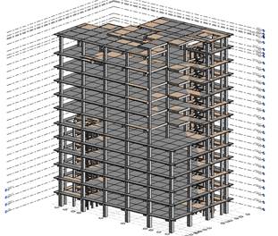
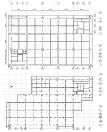
Fig. 1 Revit (BIM Model) Model for Tower Structure
Seismic parameters for tower building located in Depok, West Java, Indonesia could be seen in Table 1. The structure was analyzed using the response spectrum analysis method. Considering the building functions as a research laboratory, a uniform live load of 5 kPa and a superimposed dead load of 1.5 kPa was uniformly assigned across the floor plan. Concrete with a compressive strength of 35 MPa and BJTS 420B rebar type was employed. BJTS 420 B was equivalent to ASTM A706 Grade 60 (G60) in terms of mechanical properties and applications. Structural elements' dimensions were adjusted iteratively to achieve optimal efficiency.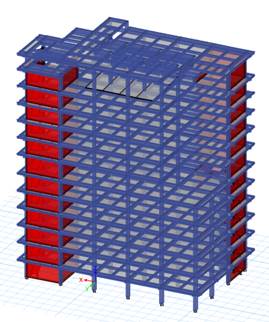
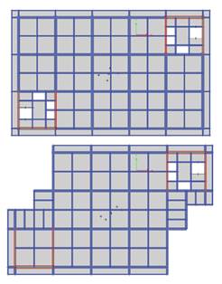
Fig. 2 ETABS Model for Tower Structure
The columns' final dimensions in the structure were 700 mm x 700 mm from story 1 to story 7, and 600-mm x 600 mm from story 8 to the top floor. Main girder dimensions were 500 mm x 700 mm, while secondary beams measure 300 mm x 500 mm. Shear wall thickness remains consistent at 400 mm for all stories. The slab was modelled as a membrane with a thickness of 130 mm. Initially, the CONV structure was designed solely as an open-frame system (without shear walls), as depicted in Fig. 1. However, due to the building's classification as Risk Category IV, the drift limitation is stringent (1% of the building height). If the structure were to remain as an open-frame system, the column dimensions would need to be excessively large. To address this issue, a special shear wall with a thickness of 400 mm (X Direction) and 600 mm (Y Direction) was added at the corners of the structure, as shown in Fig. 2.
Table 1. Seismic Parameters of Tower Building
| Parameter | |
| Risk Category | IV |
| Earthquake Priority Factor (Ie) | 1.5 |
| Location | Depok, West Java, Indonesia |
| Base Rock Acceleration Ss | Ss: 0.89 |
| S1 0.42 | |
| Site Class | |
| Site Coefficient | Fa 1.18 |
| Fv 2.36 | |
| Acceleration Response Parameters | SMS 0.782 |
| SM1 0.608 | |
| Spectral Design Acceleration | SDS 0.7 |
| SD1 0.66 | |
| Seismic Design Category | D |
| Seismic Force Resisting System | Dual System Special Moment Resisting Frame (SMRF) and Shear Wall |
| Modification Response Coefficient (R) | 7 |
| Overstrength Factor Ὠ0 | 3 |
| Deflection Amplification Factor Cd | 5.5 |
For comparative analysis, a post-tensioned flat slab model has been developed. The post-tensioned flat slab has also undergone iterations to determine the most optimal and efficient member sizes. In the final design, a 700 mm x 700 mm gravity column will be used at all stories. For lateral system resisting force, a 600 mm x 1000 mm perimeter column was assigned from story 1 to story 7, and a 500 mm x 1000 mm perimeter column was assigned from story 8 to the roof. To attain a high stiffness perimeter frame in the structure, a 400 mm x 700 mm perimeter beam was assigned at all stories. The shear wall thickness used was 400 mm, consistent with the CONV system. To distribute the high axial load to the shear wall, four collector beams measuring 800 mm x 600 mm were assigned at every floor, as Shown in Fig. 3. The comparison of the dimensions of both structural elements can be observed in Table 2
Table 2. Structural Dimension Comparison for CONV and PTFS
| Structural Element | Story | CONV (mm) | PTFS (mm) |
| Column | 1-7 | 700x700 | 600x1000 |
| 8-Roof | 600x600 | 500x1000 | |
| Main Girder | All | 500x700 | - |
| Secondary Beam | All | 300x500 | - |
| Perimeter Frame | All | - | 400x700 |
| Collector Beam | All | - | 800x600 |
| Shear Wall | All | 400 (X), 600 (Y) | 400 (X), 600 (Y) |
| Slab | All | 130 | 200 |
For the post-tensioned flat slab, the slab was modelled as a thin shell with a thickness of 200 mm. To ensure sufficient punching shear capacity, a drop panel measuring 2700 mm x 2700 mm and 150 mm in depth was provided at the gravity column. For the prestress strand, a 7-wire strand with a diameter of 15.2 mm, low relaxation, and a cross-sectional area of 140 mm2, with a specified minimum tensile strength (FPu) of 1860 MPa, was assigned at the column and middle strip. The strand was jacked to 75% of its ultimate tensile strength. Considering stress losses, transfer losses of 221 MPa and long-term losses of 154 MPa were considered. Four tendons were allocated to the column strip, spaced 1000 mm apart. Each tendon will consist of 3, 4, 4, and 3 strands from left to right, respectively. In the middle strip, four tendons were placed at 1000 mm intervals, each containing only 2 strands. The tendon profile in both the X and Y directions can be observed in Fig. 4.
The determination of the number of strands is based on 75% balancing dead load at every tributary area. In the X-direction, the tendon follows a parabolic shape, while in the Y-direction, it follows a reversed parabola. Each tendon is positioned at 55 mm from the slab surface to accommodate the concrete cover and slab rebar. With consideration for the concrete compressive strength during the jacking stage being 30 MPa, the post-tensioned stress limits were -18.49 MPa and 2.78 MPa at transfer state and -15.75 MPa and 2.96 MPa at service state.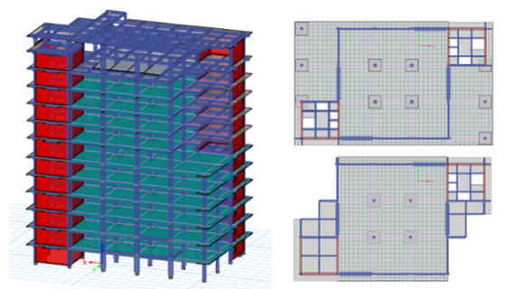
Fig. 3 Research Object (Post Tensioned Flat Slab Floor System)


Fig. 4 Tendon Layout at X Direction (Top) and Y Direction (Bottom)
The maximum tensile stress at transfer state on the top face is 1.1 MPa, while on the bottom face, it is 0.96 MPa. In the service state, the maximum tensile stress on the top face is 1.75 MPa, while on the bottom face, it is 1.66 MPa. The maximum compression stress at transfer state on the top face is -7.5 MPa, and on the bottom face, it is -3.01 MPa. In the service state, the maximum compression stress on the top face is -4.91 MPa, and on the bottom face it is -4.95 MPa. All compression and tensile stress remain within the maximum allowable stress. The stress distribution of the slab was depicted in Fig. 5 and Fig. 6
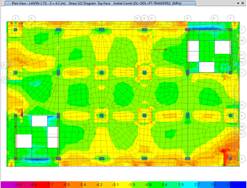
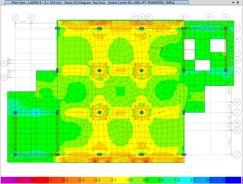
Fig. 5 Shell Stress at Transfer State (Top Surface)
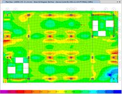
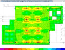
Fig. 6 Shell Stress at Service State (bottom surface)
The gravity column in the post-tensioned flat slab system was designed using the compatibility displacement method. The fundamental concept of this method involves applying a unit load drift at every story. The design of the gravity column was considered the combination of service loads (1.2 DL + 1.2 SIDL + 1.0 LL) and the load drift (𝛿u) simultaneously. Following the seismic analysis of the entire model, the maximum drift in the x-direction was 4.007 mm, and in the y-direction, it was 3.153 mm. The number of drifts has already been amplified using the Cd factor.
According to the calculations, the gravity column can withstand more than 0.3 Ag.fc' (indicating a high axial load). According to ACI 318-14 [21] clauses 18.14.2.2 and 18.14.3.3 the designer has the option to choose either:
- Meeting the requirement for δu, which allows for less restriction in confinement bars and flexibility in splicing location.
- Failing to meet the requirement for δu but ensuring 100% confinement provision is met at the expected plastic hinge position, and splicing is limited to the mid-height span of the column.
At this point, it was confirmed that the gravity column with a 2% rebar content satisfies the ultimate force acting on the column. Since the column demand for δu was satisfied, the column design allows for less restriction in confinement bars and offers flexibility in splicing location. The final design for the gravity column was 20D25 rebars as longitudinal reinforcement, D10-100 as longitudinal reinforcement, and 8D10-100 as ties.
3 Results and discussions
At this stage, a comparison was evaluated regarding the structural characteristics, structural response (drift, displacement, story shear, overturning moment), volume, and cost between conventional structural components (CONV) and Post-Tensioned Flat Slab (PTFS).
3.1 Structure response comparison
3.1.1 Structural characteristic comparison
Based on the modelling results, it was observed that the Post-Tensioned Flat Slab (PTFS) structure is stiffer than the Conventional (CONV) structure. This is evidenced by a 5.9% difference in natural period in the X direction and a 7.5% difference in the Y direction. This difference in natural period values leads to variations in the elastic seismic coefficient and base shear force. Although the mass of the conventional structure is 1.7% larger, the PTFS structure exhibits a 4.5% higher base shear force in the X direction and a 6.3% higher base shear force in the Y direction in terms of static base shear. Further details of this comparison are provided in Table 3.
Table 3. Structural Characteristic Comparison
| CONV | PTFS | |||||
| Parameters | X Dir. | Y Dir. | X Dir. | Y Dir. | X Dir Diff % | Y Dir Diff % |
| Seismic Mass (tonf) | 15860 | 15860 | 15597.1 | 15597.1 | 1.67 | 1.67 |
| T Used (s) | 1.193 | 1.106 | 1.123 | 1.023 | 5.87 | 7.5 |
| Cs | 0.12 | 0.13 | 0.13 | 0.14 | 6.23 | 8.11 |
| Static Base Shear (kN) | 18431.03 | 19880.84 | 19255.31 | 21137.54 | 4.47 | 6.32 |
Based on previous research [22], it has been found that the PTFS structure exhibits a slightly higher rigidity, approximately 6%, compared to conventional structures. A similar observation is found in this study, where the PTFS structure tends to be approximately 5.9-7.5% stiffer due to the presence of the perimeter frame as a lateral force resisting system. Despite both structural systems having the same shear wall configuration and thickness, the perimeter columns in the PTFS structure were rectangular (600 mm × 1000 mm), whereas those in the CONV structure were square (700 mm × 700 mm). The stiffness of the PTFS perimeter columns was calculated to be 0.05 m⁴E, compared to 0.02 m⁴E for the CONV columns. These calculations indicate that the perimeter columns in the PTFS structure are 2.5 times stiffer than those in the CONV structure. This stiffness difference is the primary factor contributing to the overall higher rigidity of the PTFS system compared to the CONV system.
3.2 Story Drift Comparison
Based on the comparison of story drift values in the X direction, the conventional structure exhibits higher drift values ranging from 4.3-21.7%. Similarly, in the Y direction, the conventional structure also demonstrates higher drift values ranging from 1.5-12.3%. The notable increase in drift on the 7th floor was attributed to changes in the floor plan, as indicated in the provided plan. Conversely, the flat slab structure shows lower drift values due to the presence of a rigid perimeter frame, which reduces the drift values. The comparative graph of story drift between CONV and PTFS is shown in Fig. 7
Based on a study of a 12-story structure with a symmetric plan configuration [22], the flat slab system was found to be stiffer than the conventional structure, with peak drift values reduced by up to 12.5%. This aligns with the findings of this study, which indicate that PTFS structures are stiffer by 12.3% (in the X direction) and 21.7% (in the Y direction). The asymmetrical layout of the research structure leads to differences in drift in both directions.
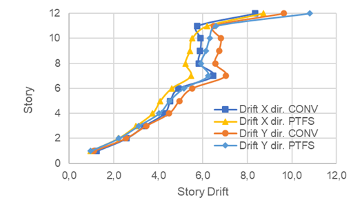
Fig 7. Story Drift Comparison between CONV and PTFS
3.3 Story Displacement Comparison
Based on the comparison of story displacement values in the X direction, the conventional structure exhibits higher story displacement values ranging from 6.7-14.1%. Similarly, in the Y direction, the conventional structure also demonstrates higher story displacement values ranging from 2.2-12.7%. The smaller displacement values in the flat slab structure are attributed to the presence of a rigid perimeter frame, which reduces the story displacement values. The comparative graph of story displacement can be viewed in Fig. 8
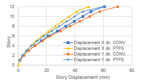
Fig. 8 Story Displacement Comparison between CONV and PTFS
3.4 Story shear comparison
Based on the comparison of story shear values in the X direction, the PTFS structure exhibits higher story shear values ranging from 0.6-6.1%. Similarly, in the Y direction, the PTFS structure also demonstrates slightly higher story shear values ranging from 0.3-4.3%, especially on 4th floor and above. The stiffer perimeter frame in the PTFS structure absorbs more dynamic forces, resulting in higher story shear values in the PTFS structure. The comparative graph of story shear can be seen in Fig. 9.
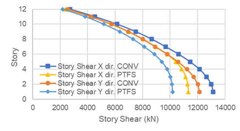
Fig 9. Story Shear Comparison between CONV and PTFS
3.5 Story overturning moment comparison
Based on the comparison of overturning moment values in the X direction, the conventional structure exhibits higher overturning moment values ranging from 9.8-22.5%. Similarly, in the Y direction, the conventional structure also demonstrates higher overturning moment values ranging from 9.1-33.1%. The overturning moment values are directly proportional to the story shear values. The higher story shear values in the flat slab structure led to an increase in overturning moment values, resulting in larger overturning moment values in the PTFS structure. The comparison graph of overturning moment can be viewed in Fig. 10.
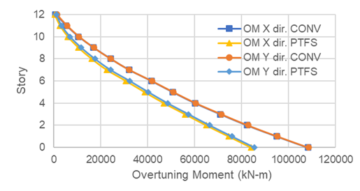
Fig. 10 Overturning Moment Comparison between CONV and PTFS
3.5.1 Volume and cost comparison
During completion of the iteration process and based on the reinforcement requirements per element (capacity-based design), reinforcement detailing was carried out with the assistance of ETABS. ETABS automatically calculates the necessary reinforcement amount for each element based on criteria outlined in ACI 318-19. Once the reinforcement detailing is completed, the reinforcement details are exported to Revit for volume calculation. The unit price for structural element work was developed based on Analysis of Work Item Costs (AHSP) as outlined in Indonesian Ministry of Public Works and Housing Regulation No. 1 of 2022. These prices will then be converted to US dollars using the prevailing exchange rate. The unit price calculation considers the cost of materials, tools, and labor. The structural element volume and cost comparison can be seen at Table 4.
Table 4. Structural Element Volume and Cost Comparison
| Work Item | CONV | PTFS | ||||||
| volume | Unit price | Cost | volume | Unit Price | Cost | |||
| Column Rebar (tonf) | 126.37 | $1,124.98 | $142,158 | 131.41 | $1,124.98 | $147,829.76 | ||
| Column Casting (m3) | 490.51 | $133.00 | $65,240 | 538.99 | $133.00 | $71,687.22 | ||
| Column Formwork (m2) | 3029.1 | $13.99 | $42,364 | 3333.8 | $13.99 | $46,624.97 | ||
| Beam Rebar (tonf) | 415.22 | $1,124.98 | $467,113 | 175.673 | $1,124.98 | $197,627.91 | ||
| Beam Casting (m3) | 1741.44 | $133.00 | $231,617 | 818 | $133.00 | $108,796.34 | ||
| Beam Formwork (m2) | 7925.94 | $28.53 | $226,124 | 2835.86 | $28.53 | $80,905.90 | ||
| Wall Rebar (tonf) | 160.33 | $1,194.70 | $191,549 | 154.3 | $1,194.70 | $184,339.60 | ||
| Wall Casting (m3) | 1478.55 | $133.00 | $196,651 | 1577.9 | $133.00 | $209,864.58 | ||
| Wall Formwork (m2) | 4800 | $29.51 | $141,667 | 4800 | $29.51 | $141,667.12 | ||
| Slab Rebar (tonf) | 202.38 | $1,194.70 | $241,781 | 141.26 | $1,194.70 | $168,759.31 | ||
| Slab Casting (m3) | 1582.87 | $133.00 | $210,526 | 2246.08 | $133.00 | $298,735.08 | ||
| Slab Formwork (m2) | 10538.7 | $23.47 | $247,339 | 11643.5 | $23.47 | $273,268.09 | ||
| Tendon (tonf) | 0 | $4,800.00 | $ - | 52.48 | $4,800.00 | $251,904.00 | ||
| Total Cost | CONV Total Cost | $2,404,128 | PTFS Total Cost | $2,182,010 | ||||
Based on the volume analysis, it can be observed that the PTFS structure requires more concrete volume (+3.8%), rebar volume (+9.9%), and formwork volume (+10.1%) in columns due to the larger dimensions of perimeter columns compared to the conventional structure. Conversely, for beam components, the PTFS structure saves concrete volume (-57.7%), rebar volume (-53.0%), and formwork volume (-64.2%) compared to the conventional structural system. For slab components, the PTFS structure requires more concrete volume (+41.9%) and formwork volume (+10.5%), but less rebar volume (-30.2%). For wall components, the PTFS structure requires slightly larger shear wall dimensions (+3.8%) but a smaller amount of rebar (-6.7%) compared to the conventional structure. Employing the PTFS structure allows for cost savings of $222,118 for structural components, representing 10.2% of the total structural work cost. The total price and volume comparison for the conventional (CONV) and Post-Tensioned Flat Slab (PTFS) structure are provided in Table 5.
Table 5. Total Volume and Price Comparison
| Total Volume Comparison | |||
| Unit Item | CONV | PTFS | Diff (%) |
| Total Rebar (tonf) | 904.3 | 602.6 | 33.4 |
| Total Concrete Casting (m3) | 5293.4 | 5181.0 | 2.1 |
| Total Formwork (m2) | 26293.7 | 22613.2 | 14.0 |
| Total Price Comparison | |||
| Unit Item | CONV | PTFS | Diff (%) |
| Total Rebar (tonf) | $ 1,042,601.5 | $ 698,556.6 | 33.0 |
| Total Concrete Casting (m3) | $ 704,033.2 | $ 689,083.2 | 2.1 |
| Total Formwork (m2) | $ 657,493.4 | $ 542,466.1 | 17.5 |
According to the literature [22], the PTFS system with an 8 m span shows concrete cost savings of up to 11% and rebar costs reduced by 27%. However, in the actual calculations, the cost difference indicates concrete savings of 2.2% and a total reduction in rebar costs by 33.0%. This difference can be attributed to differences in layout, the number of floors, and the applied seismic loads. Based on this study, the static base shear of the Post-Tensioned Flat Slab (PTFS) system was 4.47%–6.32% higher than that of the conventional (CONV) system. However, in the final cost comparison, the PTFS system was found to be 10.2% more cost-effective than the CONV system. Although the PTFS system exhibits slightly greater stiffness and higher resistance to seismic forces compared to the CONV system, it offers greater cost savings in structural elements primarily designed to resist gravity loads, such as the main girders and secondary beams. While the PTFS system incurs additional costs for column reinforcement and concrete casting, the cost difference in the lateral force-resisting system (columns and walls) remains lower than the cost difference in the gravity-resisting system (post-tensioned flat slab). This finding indicates that the PTFS system is a more economically viable construction solution, even in high-seismic zones.
4 Conclusions
Based on the research findings, several conclusions can be drawn as follows:
- The Post-Tensioned Flat Slab (PTFS) structure has a smaller seismic weight compared to the conventional structure (CONV) by 1.67%. However, the PTFS structure tends to be stiffer, as indicated by the shorter natural period (5.8% - 7.5%). This results in an increase in the elastic seismic coefficient (6.23% - 8.11%) and an increase in static base shear force (4.5% - 6.3%).
- Due to the greater stiffness of the PTFS structure, there was a reduction in drift values in the PTFS structure (1.5% - 21.7%) and story displacement values (2.2% - 14.1%). The increase in stiffness leads to an increase in story shear values (0.3% - 6.1%), accompanied by an increase in overturning moment values (9.1% - 33.1%).
- The PTFS structure results in more efficient designs in terms of concrete, rebar, and formwork volume for beams (57.7% - 64.2%). However, greater volumes of concrete, rebar, and formwork are required for column work (3.8% - 10.1%). For slab work items, the PTFS structure requires more concrete and formwork (41.9% and 10.5%, respectively) but less rebar (30.2%). Similarly, for shear wall work items, the PTFS structure requires more concrete volume (6.7%) but less rebar (3.8%).
- The post-tensioned flat slab system could provide cost savings of up to $222.118 or 10.2% of the total structural work cost.
- Based on the total cost calculations for each work item, it was found that the PTFS structural system provides cost savings of 33% for rebar, 2.1% for concrete casting, and 17.5% for formwork.
- In the subsequent research, the performance of each structure model will be examined using non-linear static pushover analysis.
Acknowledgements
This research was funded by the Directorate of Research and Development, Universitas Indonesia, under HIBAH PUTI Pascasarjana No. NKB-121/UN2.RST/HKP.05.00/2024.
References
- Crotty, R. (2012). The impact of building information modelling: Transforming construction. Taylor & Francis.
- Migilinskas, D., Popov, V., Juocevicius, V., & Ustinovichius, L. (2013). The benefits, obstacles and problems of practical BIM implementation. Procedia Engineering, 57, 767–774. https://doi.org/10.1016/j.proeng.2013.04.097
- Kermanshahi, E. K., Tahir, M. B. M., Shukor Lim, N. H. A., Balasbaneh, A. T., & Roshanghalb, S. (2020). Implementation of Building Information Modeling for Construction Clash Detection Process in the Design Stage: A Case Study of Malaysian Police Headquarter Building. IOP Conference Series: Earth and Environmental Science, 476(1), 012009. https://doi.org/10.1088/1755-1315/476/1/012009
- Tommelein, I. D., & Gholami, S. (n.d.). Root causes of clashes in building information models. Bentley Systems. Retrieved from https://www.bentley.com/en-US/Products/ProjectWise+Navigator/
- Hadi, A. S., Abd, A. M., & Mahmood, M. (2021). Integrity of Revit with structural analysis softwares. IOP Conference Series: Materials Science and Engineering, 1076(1), 012119. https://doi.org/10.1088/1757-899X/1076/1/012119researchgate.net
- Gegana, G., & Widjinarso, T. H. (2015). BIM course development and its future integration at University of Indonesia and Institute of Technology Bandung Indonesia. In 9th BIM Academic Symposium & Job Task Analysis Review, Washington.
- Sulistian, R., Sjah, J., Rarasati, A. D., & Oetomo, J. J. (2022). A study of BIM modelling in seismic. International Journal of Science and Engineering Investigations, 11. Retrieved from http://www.ijsei.com/papers/ijsei-11122-01.pdf
- Wu, C.-L., Wang, K.-C., & Wang, W.-C. (2018). A BIM-based conceptual cost estimation model considering structural analysis and design. In Proceedings of the 35th ISARC, 278–285. https://doi.org/10.22260/ISARC2018/0040iaarc.org
- Bahoria, B. V., & Parbat, D. K. (2013). Analysis and design of RCC and post-tensioned flat slabs considering seismic effect. International Journal of Engineering and Technology, 5(1), 10–13. https://doi.org/10.7763/IJET.2013.V5.500
- Shruti Vijaykumar, D., & Jawalkar, G. C. (2019). Comparative analysis of RCC flat slab with post-tensioned flat slab. International Journal of Scientific Research in Science, Engineering and Technology, 6(3), 241–249. https://doi.org/10.32628/ijsrset196356
- Satwika, V., & Jaiswal, M. (2022). Comparison of RCC and post-tensioned flat slabs using ETABS. IOP Conference Series: Earth and Environmental Science, 982(1), 012084. https://doi.org/10.1088/1755-1315/982/1/012084
- Török, I., Puskás, A., & Virág, J. (2019). Post-tensioned flat slabs with unbonded tendons for public buildings. Procedia Manufacturing, 32, 102–109. https://doi.org/10.1016/j.promfg.2019.02.189
- Reddy, J. (2017). Comparative study of post-tensioned and RCC flat slab in multi-storey commercial building. International Research Journal of Engineering and Technology, 4(5). Retrieved from https://www.irjet.net/archives/V4/i5/IRJET-V4I5101.pdf
- Thayapraba, M. (2014). Cost effectiveness of post-tensioned and reinforced concrete flat slab systems. International Journal of Engineering Research and Applications, 4(6), 124–128. Retrieved from https://www.ijera.com/papers/Vol4_issue6/Version%201/V04601124128.pdf
- Thakkar, V. P., Chandiwala, A. K., & Bhagat, U. D. (2017). Comparative study of seismic behavior of flat slab and conventional RC framed structure. International Journal of Engineering Research & Technology, 6(4), 739–743. https://doi.org/10.17577/IJERTV6IS040739ijert.org
- Apostolska, R. P., Necevska-Cvetanovska, G. S., Cvetanovska, J. P., & Mircic, N. (2008). Seismic performance of flat-slab building structural systems. In 14th World Conference on Earthquake Engineering, Beijing, China.
- Vijayan, D. S., Arvindan, S., Naveen Kumar, K., & Mohamed Javed, S. (2019). Seismic performance of flat slab in tall buildings with and without shear wall. International Journal of Engineering and Advanced Technology, 9(1), 2672–2675. https://doi.org/10.35940/ijeat.A9732.109119
- Sahni, B. R., Hiwase, P. D., & Dahale, P. P. (2018). Seismic behaviour of flat slab building with shear wall. International Journal of Civil Engineering and Technology, 9(5), 1049–1055. Retrieved from http://iaeme.com/MasterAdmin/Journal_uploads/IJCIET/VOLUME_9_ISSUE_5/IJCIET_09_05_117.pdf
- Galvis, F., Miranda, E., Heresi, P., Dávalos, H., Silos, J. R., & Blume, J. A. (2017). Preliminary statistics of collapsed buildings in Mexico City in the Puebla-Morelos earthquake. Earthquake Spectra, 34(4), 1551–1570. https://doi.org/10.1193/121817EQS269M
- Akbas, B., Doran, B., Bozer, A., Seker, O., Faytarouni, M., & Shen, J. (2020). Seismic performance evaluation of reinforced concrete moment frames with gravity columns. ASCE Structural Journal, 146(3), 04020020. https://doi.org/10.1061/(ASCE)SC.1943-5576.0000452
- ACI Committee 318. (2015). Building code requirements for structural concrete (ACI 318M-14): An ACI standard: Commentary on building code requirements for structural concrete (ACI 318M-14). American Concrete Institute.
- Abdelaziz, O. K., & Abdalla, H. A. (2021). Cost evaluation of post-tensioned slabs in multi-storey buildings considering seismic effect. In Proceedings of the 4th International Conference on Civil and Environmental Engineering for Sustainability (IConCEES 2021), 742–750. https://doi.org/10.38027/ICCAUA2021280n5
- Rath, S. R., Sethy, S. K., & Dubey, M. K. (2019). Comparative study on analysis and designing of post-tensioned flat slab vs conventional slab. International Journal of Research in Advent Technology, 7(5), 1–6. Retrieved from http://www.ijrat.org/downloads/Vol-7/may-2019/paper%20ID-75201945.pdf
Conflict of Interest Statement
The authors declare that there are no conflicts of interest that could have influenced the outcomes or interpretation of this research.
Author Contributions
Data Availability Statement
The data supporting the findings of this study are available from the corresponding author upon reasonable request.
Supplementary Materials
No supplementary materials are associated with this study.