Volume 24 number 1 article 1319 pages: 107-116
Received: Feb 04, 2026 Accepted: Feb 12, 2026 Available Online: Feb 01, 2026 Published: Mar 02, 2026
DOI: 10.5937/jaes0-62455
DEVELOPMENT OF A DEVICE FOR COOLING LADLE LINERS FOR CASTING LADLES
Abstract
This article focuses on the controlled cooling process of the linings of ferroalloy production ladles. Analysis of the operating conditions of the linings revealed that temperature stresses during heating and cooling are the main cause of damage to the linings of high-temperature units. At the enterprise in question, the cooling process is uncontrolled when the lining is exposed to the workshop atmosphere. This leads to cracks forming in the lining and its subsequent destruction. Cooling schedules have been developed for the ladles under consideration, during which the resulting thermal stresses do not damage the lining. A device has been developed for the ladle liners to ensure the cooling process is kept on schedule. Incomplete liner replacement involves cooling the ladle by supplying a mixture of combustion gases from the ladle heating booth and air. The liner is cooled using a mixture of three media: ambient air from the workshop, combustion products from the ladle heating stand, and combustion products from the ferroalloy gas burnt in the burner. A cooling schedule for casting ladle liners has been developed to ensure that thermal stresses do not exceed the strength limit of the refractory materials. At the same time, the cooling time is reduced from 19 hours 30 minutes to 6 hours 50 minutes. The developed device enables the outer and inner walls of the lining to be cooled, secondary resources (ferroalloy gas and combustion products from the ladle heating stand) to be used.
Highlights
- The main reason for the destruction of the linings of the casting ladles under consideration is thermal stresses.
- A device has been developed for controlled cooling of the lining of filling ladles.
- To cool the liner, a mixture of three media is used: ambient air from the shop, combustion products after the ladle heating stand and combustion products of ferroalloy gas burnt in the burner.
- An economic assessment of the use of secondary energy resources in a device for cooling the lining of filling ladles has been made.
Keywords
Content
1 Introduction
The lining of high-temperature units is designed to contain the process material within the working space of the unit. For many such units, the technical condition of the lining is crucial when the unit is removed for maintenance. This is particularly true for converters, casting and intermediate ladles, and arc furnaces [1–4].
Analysis of the research conducted enables us to identify the primary sources of failure of the lining of high-temperature units [5–10]:
- presence of a temperature difference along the cross-section of the lining during non-stationary thermal processes (drying, heating, cooling and draining of the technological product);
- high lining temperature;
- influence of aggressive working environments;
- mechanical effects on the lining;
- other operational factors.
The temperature gradient in the lining during unsteady processes causes thermal stress in the refractories. These stresses arise due to the uneven thermal expansion of the lining layers. They also arise when the lining's temperature changes rapidly, whether it is rising or falling. [11]
During heating, the surface layer of the lining is under compressive stress (σc), while during cooling it is under tensile stress (σten). For refractory linings, rapid cooling is more dangerous than rapid heating. This is due to the significant difference between the compressive strength of refractories and their tensile strength. [12]
The cooling of the liner of a high-temperature unit (such as a ladle) with significant temperature differences across the cross-section of the liner occurs in three cases:
- cooling of the lining after melt draining (i.e. cooling during downtime between melts);
- cooling of the lining before intermediate repairs (e.g. replacement of part of the lining or the casting cup);
- cooling of the lining before an overhaul.
We do not consider cooling the ladle liner with molten metal, since this process does not involve significant temperature stresses due to the high temperature and heat content of the molten metal.
A key objective at every stage of ladle operation is to minimise its duration, which has a positive impact on its technical and economic performance.
Cooling the lining before an overhaul can be carried out at the highest possible speed, since this type of overhaul involves the lining being completely removed.
Cooling the lining during downtime between melts and before intermediate repairs must be carried out at limited speeds to avoid destruction of the lining. In real production conditions, this cooling process usually occurs under the natural convection of the shop atmosphere. Depending on the ladle's capacity, the refractory material used and the lining's thickness, the cooling rate can vary significantly. For example, the temperature drop rate of an arc furnace lining under natural convection is 360°C per hour within a temperature range above 1000°C. [13]
The authors in [14] give the rate of uncontrolled cooling of the casting ladle liner after melting drain, which is 318°C/hour from 1300°C to 875°C.
In [15], the destruction of a vacuum chamber lining with a working layer of periclase-chromite refractories was studied. During cooling, the temperature only decreases by more than 110°C for the first 10 seconds, resulting in a thermal shock. Tensile stresses act on the material in this case, forming rare deep cracks in the refractory. Their depth can reach up to 120 mm. According to the authors' research, the crack formation time is 7 to 10 seconds from the beginning of cooling.
The article [16] evaluated the thermal stress state of a rotary kiln lining. The authors presented the results of modelling the process of linear cooling of the hot surface of the lining from the temperature (1250°C) to the ambient temperature (20°C). Five possible cooling rates were investigated: from 39 to 625°C/h. Thus, the cooling durations varied from 2 to 32 hours. It was found that tensile stresses can become critically high and lead to failure of the lining material.
When cooling the casting ladle from the lining’s initial temperature (about 900°C), the average temperature decrease after the melting drain (on the hot side) was 274°C/h. [17] A similar rate of temperature decrease was recorded during all five steel working cycles.
The authors [18] divided the thermal operation of the steel ladle liner into several stages. At the first stage (warm-up), the temperature of the working liner increases from 40°C to 1400°C. The next stage is the transport of the ladle to the high-temperature unit with heat loss to the environment and temperature reduction to about 1200°C. Then, when the melt is poured into the ladle, the temperature of the liner rises sharply to a value of 1650°C. At the end of the thermal cycle, the temperature of the inner surface of the liner gradually decreases after the liquid steel is poured. For the walls, the cooling rate was 20°C/min, for the bottom, the rate was 16.5°C/min.
As can be seen from the above data analysis, the rates of uncontrolled cooling of liners of various high-temperature aggregates differ significantly. Nevertheless, all the mentioned processes are characterised by high cooling rates: 200°C and higher.
The controlled cooling of the lining is recommended to be carried out at a rate not exceeding 50°C/h. [19] The heating rate of the lining during the drying process was not more than 10°C/h. The results of inspection of the rotary kiln at the end of the lining drying process and its cooling from 400°C to 40°C showed that no defects, local overheating, or integrity failures were found.
Analyses of the working cycle of a casting ladle at various enterprises show that the cooling of ladle linings before and after the melt is poured into them is uncontrolled. The duration of waiting for the melt to be poured into the ladle can reach 30 minutes [6]. To reduce the cooling rate, the ladle with the heated lining is covered with a lid with a layer of thermal insulation. [20, 21]
It is recommended that ladle idle time without a lid be minimised since, in this case, there is a significant reduction of enthalpy in the ladle between the end of heating and discharge. [22] It is noted that the ladle lining can be cooled up to five times per shift. [6] Stresses arising in refractories during cooling can be a source of cracks, leading to lining damage. It is recommended to organise the ladle turnover in such a way as to exclude cooling of the ladle lining below 600°C.
From this review, we can conclude that enterprises operating high-temperature units pay little attention to the cooling processes of liners. The cooling process is often uncontrolled and without developed modes. In most cases, the cooling rates of the liners are high, and the resulting thermal stresses exceed the permissible level. This leads to cracking and failure of the liners.
The significant difference between cooling rates under conditions of natural convection of the shop atmosphere and recommended rates obtained based on modelling suggests the need to develop special devices for controlled cooling of high-temperature unit liners.
2 Materials and methods
Let's consider the operation of a 40-tonne ferroalloy production ladle to analyse the cooling processes of ladle liners. The ladle lining is constructed in ten rows of height from aluminosilicate clinker bricks of ShKU-32 grade. It consists of two layers of fireclay bricks (80 mm each) with a total thickness of 160 mm.
The duration of the working campaign for the ladle liners under consideration is from 4 to 10 melts and depends on the type of smelted ferroalloys: ferrochrome, ferrosilicomanganese, and ferrosilicon.
The average time of molten metal in the casting ladle of one melting is 100–120 minutes. The average temperature of the drained melt is 1700°C.
The ladle liners are cooled under natural convection conditions in the atmosphere of the melting shop. There is no cooling equipment. Depending on the time of year, the shop's temperature can vary from -7°C to 32°C.
Analysis of existing cooling methods for casting ladle liners in ferroalloy production shows that cooling is very uneven and uncontrolled under natural convection conditions. The inner surface temperature of the lining decreases by 300°C in 30 minutes at the initial stage of cooling. At the final cooling stage, the cooling rate of the inner surface is 20 times lower than initially.
During the research, the authors surveyed ladle liners while they were in operation. [5]
The refractory lining of casting ladles deteriorates during operation and significant fragments are destroyed in some places. When ladles are removed for repair, cracks cover the entire inner surface of the lining. The average rate of lining wear is 3–5mm per melting.
Before the refractory layer of the lining is put out for repair, cracks are observed that are not accompanied by flaking. The cracks can be up to 150mm long and 35mm deep (Figure 1).
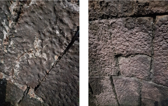
Fig. 1. Cracks in the working layer of the lining when the ladle is taken out for overhaul: a – slag belt zone; b – middle part of the ladle in height
Crack characteristics, as well as the analysis of liners' thermal modes of operation, allow us to conclude that a significant temperature difference at a sharp cooling of the lining causes crack formation [5].
Figure 2 shows the cooling schedule of the ladle lining of the casting ladle of ferroalloy production when it was put into intermediate repair (replacement of refractories of the slag belt). Temperature measurements were made in the zone of its most excellent wear – the middle zone along the height of the ladle: 5–7 rows of lining. Measurements of the temperatures of the outer surface of the casting ladle at a similar height were also carried out. The measurements were made with the help of an infrared pyrometer, Kelvin Compact 1500/175.
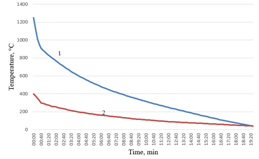
Fig. 2. Cooling schedule: 1 − graphs of temperature change on the inner; 2 − outer surface of the ladle lining during its cooling
The following conclusions can be drawn from analysing the obtained cooling graphs. Cooling the ladle lining without controlling the temperature decrease under natural convection conditions results in uneven cooling. The temperature of the inner surface decreases by 300°C within the first 30 minutes of cooling. At the final cooling stage, a temperature reduction of 300°C occurs within 610 minutes. Consequently, the cooling rates of the inner lining surface at different stages differ by more than 20 times.
A mathematical model of the lining's thermal stress state during cooling was developed to calculate rational cooling rates.
Assuming that heat is transferred to the lining only along its thickness and that there are no internal heat sources, the Fourier equation can be written as a one-dimensional unsteady heat transfer equation.
| $\rho c \frac{\partial T}{\partial t} = \frac{\partial}{\partial x} \left( \frac{\partial T}{\partial x} \right) $ | (1) |
Considering the two layers of the lining wall, the initial and boundary conditions can be written as follows:
- t = 0; T = f(x); 0 ≤ x ≤L;
- x = 0; T = T1; t > 0;
- x = F; T = Tn; t> 0;
- T1(t, x*) = T2 (t, x*).
| $-\lambda \left. \frac{\partial T_1}{\partial x} \right|_{x = x^*} = -\lambda \left. \frac{\partial T_2}{\partial x} \right|_{x = x^*} $ | (2) |
This problem is solved using the numerical method of the implicit four-point difference scheme. This method enables us to obtain accurate results regardless of the linear thickness step value or time chosen.
The main starting point for determining temperature stresses under different temperature distribution laws over the thickness of refractory masonry is the equilibrium of internal forces in the lining:
| $P=\int \sigma \, dx = 0, \quad Q=\int \sigma \, dx = 0$ | (3) |
where:
- P – the effort
- Q – moments
- σ – stresses
- x – a spatial variable.
We obtain the calculation formulae based on the solution of the plane thermoelasticity problem [2]. In this case, the problem is reduced to the solution of the Equation
| $\frac{d^2}{dx^2}\left[\sigma(x,t)-\frac{\alpha_T E}{1-\nu}\,T(x,t)\right]=0 $ | (4) |
where:
- t is a time parameter
- αT – coefficient of linear expansion
- E – the modulus of elasticity
- ν is the Poisson's ratio.
After integrating equation (4), we obtain
| $\sigma(x,t) = \varepsilon E = -\frac{\alpha_T E}{1-\nu}\,T(x,t) + \left(C + C_1 x\right) $ | (5) |
where:
- ε is the deformation due to the monolithic nature of the lining;
- C and C1 are integration constants determined from the boundary conditions
| $\sigma(H,t)=0 $ | (6) |
where:
- H is the thickness of the lining.
The temperature stresses in the lining are calculated according to the method given in [7] using the formula
| $\sigma = -\frac{\alpha E}{1-\nu}\,T(y,t) $ | (7) |
The calculations’ results are the values of temperature stresses, which are compared with the ultimate strength of the refractory materials used.
Based on the temperature data for the inner and outer surfaces of the lining, the temperature fields across the lining cross-section were calculated. The calculation error was estimated using the Runge method (repeated calculation method) [23]. The margin of error in the temperature calculation method was no more than 1%.
Based on the developed methodology, the authors calculated the resulting thermal stresses and compared their values with the ultimate strength of the refractory materials used. The resulting thermal stresses were compared with the strength limit of SHKU-32 fireclay bricks. The compressive strength limit is 27MPa, while the tensile strength limit is 6MPa.
For refractories after three melts, the maximum value of compressive thermal stress exceeds the compressive strength 1.28 times, and the maximum value of tensile thermal stress exceeds the tensile strength 3.19 times [25].
Analysis of similar scientific studies confirms the data obtained. Thus, the authors of the works [16, 24] show that the thermal stresses generated during the heating process can exceed the strength limit of the refractory materials used by a factor of three or more.
Figure 3 shows the distribution of thermal stresses across the thickness of the lining 20 seconds after the start of cooling.
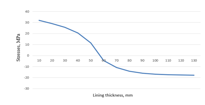
Fig. 3. Distribution of thermal stresses across the thickness of the lining 20 seconds after the start of cooling
Rational cooling schedules were developed to eliminate the destructive effects of thermal stresses during cooling, taking into account the dependence of the thermophysical and thermomechanical properties of the refractory materials used on temperature. Using the expanded schedule reduces the cooling time from 19 h 30 min to 6 h 50 min when thermal stresses do not exceed the strength limit of the refractory materials used. Figure 4 shows the cooling schedule developed for the lining with refractories that have been used for three melts [26].
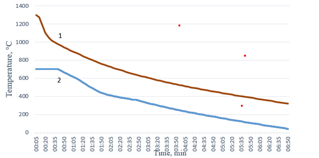
Fig. 4. Developed a graph of the change in temperature of the external surface of the furnace lining during cooling (for refractories after three melts)
During the initial period, the outer wall of the lining must be heated to reduce thermal stresses. From the moment the molten metal drains away, the lining cools down significantly and the temperature distribution becomes more uneven.
Heating the outer surface of the lining leads to a more uniform temperature distribution throughout its thickness and reduces thermal stresses. This stage lasts 25 minutes.
Optimising the cooling of high-temperature unit linings will enable the cooling process to be carried out at a speed at which the resulting thermal stresses will not destroy the masonry. In addition, calculations show that reducing the lining cooling time and increasing casting ladle productivity is possible.
3 Results and discussion
An important task is to reduce the lining temperature following the developed schedules. Many methods and devices have been designed to heat the liners of high-temperature units [26–28]. An automation system allows the cooling process to be conducted quite accurately. Modern devices provide a uniform temperature field of the inner surface of the lining [29]. Thus, according to [30], the temperatures of the hottest and coldest points of the inner surface of the ladle liner during its heating differ by no more than 10%. It is not possible to cool the liner on the ladle heating bench, as the burners used will not be able to provide the required heat flux range at liner temperatures below 400°C. In addition, as mentioned above, the initial stage of cooling of the inner surface must be accompanied by heating the outer wall of the liner to reduce thermal stresses. Patent reviews have shown that the devices developed for cooling metallurgical ladle liners have not found wide applications in the industry [31, 32]. The main task of the developed devices is to reduce the heating time, for which purpose cooling by atomised liquid is allowed. Cooling the liner using only a lid with thermal insulation will not allow the cooling process to proceed according to schedule. [33] notes that cooling with a lid is very efficient in terms of energy saving, but its use allows the internal surface temperature to be 90°C higher than without the use of a lid. For cooling, it is necessary to select working media that can be mixed to produce a cooling medium with a temperature range from 700°C to 40°C. One such medium is shop air. To increase its thermal potential, it is necessary to mix it with a hot medium. For this purpose, combustion products from the booth for drying and heating casting ladles can be used. On the bench for drying and heating casting ladles, the temperature of the ladle lining is increased before pouring melt from the ferroalloy furnace into the ladles. This is done by burning ferroalloy gas with a calorific value of 8.3 MJ/m3. The pressure of the gas supplied to the burner is 5kPa, and the average flow rate is 540m3/h. Gas combustion occurs in the flame with temperatures from 650 to 1500°C. According to literature sources [14], the thermal efficiency of ladle heating stands depends on the heating rate. The dependence of the heating efficiency on the heating rate is explained by the peculiarities of external and internal heat exchange processes. From 23% to 48% of the energy supplied by the gas burner is used to increase the energy intensity of the refractory material. About 0.3% is accumulated by the bench lid, 5–6 % is lost to the environment, and the rest of the heat escapes with exhaust gases. Considering the above-mentioned conditions of casting ladle operation, a device for cooling the ladle lining of the casting ladle used in ferroalloy production was developed. [34] Cooling the ladle for incomplete liner replacement involves supplying a mixture of combustion gases from the ladle heater and air. The high-temperature cooling medium is initially fed to the liner’s high-temperature zones. At the same time, the cooling process is monitored in accordance with the technological regulations based on thermocouple readings installed on the ladle's bottom lining surface. The following device (Figure 5) was developed to cool the lining of the casting ladle used in ferroalloy production. It can heat the inner surface and cool the outer surface.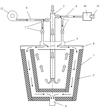
Fig. 5. Device for cooling the ladle liner of the casting ladle of the ferroalloy plant: 1 − metal housing; 2 – lining; 3 – gas duct; 4 – supply gas duct; 5 – supply manifold; 6 − supply duct; 7 − аdjusting dampers; 8 – lid; 9 − outlet opening; 10 – chamber; 11 − burner; 12 – fan
The device contains a metal housing 1 with a lining 2. Lining 2 prevents the metal body from high temperatures. Gas duct 3 is designed to supply combustion products from the ladle heating and drying stand. High-temperature medium supply gas duct 4 is connected to the combustion products supply gas duct 3 from the ladle heating and drying stand. The high-temperature medium supply gas duct 4 is also connected to the cooling medium supply manifold 5 to the outer surface of the liner 2. The air supply duct 6 supplies air intended for cooling the liner 2. Air duct 6 is connected to gas duct 3 to supply the cooling medium to the inner surface of lining 2, and to manifold 5 to supply the cooling medium to the outer surface of lining 2.
Gas ducts and air ducts supply cooling medium to the inner and outer surfaces of the liner 2. Adjusting dampers 7 allows the temperature of the coolant provided to be changed by changing the flow rates of the cooling medium's constituent parts.
The device for cooling the ladle lining has a lid 8, which covers the casing when the ladle is placed therein. Housing 1 has an outlet opening 9 for the cooling medium.
To increase the temperature of the cooling medium, a combustion chamber 10 with a burner 11 for burning ferroalloy gas is connected to the gas duct 3.
The fan 12 is designed to reduce the temperature of the cooling medium by mixing it with the supplied air.
The device for cooling the lining of the casting ladle of ferroalloy production works as follows. The casting ladle of ferroalloy production is placed inside the housing 1, which is closed with a lid 8. To cool the ladle liner, cooling medium is supplied to its inner surface through gas duct 3. The temperature of the cooling medium is regulated by changing the flow rates of three streams: combustion products flow in the gas duct 3 from the ladle heating and drying stand, air flow from the fan 12 and combustion products flow from the combustion chamber 10.
The temperature of combustion products in the gas duct 3 from the ladle heating and drying stand depends on the stage of the ladle heating process. If this temperature is below the value required for cooling following the cooling schedule, the air flow from the fan 12 is closed. If the temperature does not reach the required level, the burner 11 is switched on and thus the temperature of the cooling medium supplied to the inner surface of the liner through the gas duct 3 is increased. The media flow is changed by adjusting dampers 7.
After passing the inner surface of the lining, the cooling medium is fed to the outer surface of the lining 2. The temperature of the cooling medium supplied to the outer surface of the lining 2 is controlled by changing the air flow from the fan 12 and the flow of combustion products from the combustion chamber 10.
The outlet opening 9 is through which the cooling medium is discharged from the device for cooling the lining of the casting ladle used in ferroalloy production.
The developed device uses two types of secondary energy resource. Firstly, it uses ferroalloy gas, a by-product of ferrochrome or ferrosilicon production in a ferroalloy furnace, as a secondary fuel energy resource. This is a by-product of producing ferrochrome or ferrosilicon in a ferroalloy furnace. Its composition and properties depend on the type of alloy being smelted and the stage of the process. Secondly, the device uses thermal energy in the form of the combustion products of ferroalloy gas, which are supplied from the ladle heating and drying stand. The heat from these gases is then used to cool the ladle lining sequentially.
According to technological regulations, the lining is cooled in case of incomplete replacement by decreasing the temperature of the cooling medium over time. The cooling medium temperature changes the volumes of combustion products and air supplied. The developed device will increase the accuracy of compliance with the cooling schedule of the ladle liner of the casting ladle of ferroalloy production.
4 Conclusions
Analysis of the thermal operation of ladle liners at various enterprises shows that cooling before intermediate repairs and after melt draining is uncontrolled. The temperature stresses that arise during cooling of the liners exceed the permissible level, which leads to the destruction of the refractory material.
Research into the condition of ferroalloy ladle liners reveals deep cracks in the refractory layer's surface that do not peel off. The appearance of these cracks, together with an analysis of the cooling rates of the linings, indicates the occurrence of thermal tensile stresses that exceed the strength limit of the materials used.
A cooling schedule for casting ladle liners has been developed to ensure that thermal stresses do not exceed the strength limit of the refractory materials. At the same time, the cooling time is reduced from 19 hours 30 minutes to 6 hours 50 minutes. During the initial period, the outer wall of the lining must be warmed up to reduce thermal stresses. This is because, from the moment the molten metal is poured, the lining cools significantly and the temperature distribution becomes more uneven. Heating the outer surface of the lining leads to a more uniform temperature distribution throughout its thickness and reduces thermal stresses.
To maintain the scheduled cooling process of the casting ladle, a device was developed to cool the ladle liner. The ladle liner is cooled using a mixture of three media: ambient air from the workshop, combustion products from the ladle heating stand, and combustion products from ferroalloy gas burnt in the burner. The device cools the inner and outer walls of the lining and uses secondary resources (ferroalloy gas and combustion products from the ladle heating stand). It also conducts the cooling process according to rational modes.
This device can be used to cool the linings of various casting ladles during intermediate repairs involving the partial replacement of the lining. For example, it can be used to cool steel casting ladles. To this end, a mixture of three gaseous media is employed: ambient air from the workshop, combustion products from the ladle heating and drying stand, and combustion products from the fuel burned in the burner. Natural gas or a propane-butane mixture is typically used to heat and dry steel ladles. The developed device can burn any gaseous fuel in the burner instead of ferroalloy gas.
The limitation of the device is that it cannot be used for the complete replacement of the entire lining, i.e. intermediate repairs. Additionally, these studies cannot be applied to production facilities that do not preheat the lining on heating and drying stands.
Preliminary calculations show that using the developed device could increase the lining's durability by 5 % due to reduced thermal stresses [35] due to controlled cooling, the payback period will be no more than two months. The low payback period is explained by the use of secondary energy resources. This also contributes to a reduction in harmful emissions into the environment by reducing fuel consumption.
The energy efficiency of the developed device must be assessed during the operation of the installation in production by measuring the thermal potential of gas flows. At the same time, it is worth considering the useful use of the thermal potential of combustion products from the stand for heating and drying ladles, which accounts for about 50 % of the heat generated on the stand.
Acknowledgements
This research was funded the Science Committee of the Ministry of Science and Higher Education of the Republic of Kazakhstan (Grant No. AP19675777).
References
- Wilson D., Guillin-Estrada., Rafael Albuja., Ivan B. Dávila., Bernardo S. Rueda., Lesme Corredor., Arturo Gonzalez-Quiroga., Heriberto Maury. (2022). Transient operation effects on the thermal and mechanical response of a large-scale rotary kiln, Results in Engineering, Volume 14. https://doi.org/10.1016/j.rineng.2022.100396.
- Pagliosa, Carlos & Resende, C & Da Luz, Ana & Pandolfelli, Victor. (2017). Designing stronger and tougher MgO-C bricks for basic oxygen furnace (BOF). Refractories World Forum. 9. 89-93. https://www.researchgate.net/publication/314522579
- Kukartsev, V.A., Kukartsev, V.V., Tynchenko, V.S., Kurashkin, S.O., Sergienko, R.B., Tynchenko, S.V., Panfilov, I.A., Eremeeva, S.V., Panfilova, T.A. (2023). Study of the Influence of the Thermal Capacity of the Lining of Acid Melting Furnaces on Their Efficiency. Metals, 13, 337. https://doi.org/10.3390/met13020337.
- Nikiforov, A., Prikhodko, Y., Kucherbayev, M., Kinzhibekova, A., Karmanov, A., & Uakhit, N. (2024). Analysis of the thermal performance of the lining and the reasons for its destruction in petroleum coke calcination furnaces. EUREKA: Physics and Engineering, (5), 125-135. https://doi.org/10.21303/2461-4262.2024.003329.
- Prikhodko, E., Nikiforov, A., Kinzhibekova, A., Paramonov, A., Aripova, N., Karmanov, A. (2023). Analysis of the Effect of Temperature on the Ultimate Strength of Refractory Materials. Energies, 16, 6732. https://doi.org/10.3390/en16186732.
- VLČEK, Jozef., JANČAR, Dalibor., BURDA, Jiří., KLÁROVÁ, Miroslava., VELIČKA, Marek et al. (2016). Measurement the thermal profile of steelmaking ladle with subsequent evaluation the reasons of lining damage. Online. Archives of Metallurgy and Materials. roč. 61, č. 1, s. 279-282. ISSN 2300-1909. Dostupné z: https://doi.org/10.1515/amm-2016-0053
- Demeter, J., Buľko, B., Demeter, P., Hrubovčáková, M. (2023). Evaluation of Factors Affecting the MgO–C Refractory Lining Degradation in a Basic Oxygen Furnace. Appl. Sci. 13, 12473. https://doi.org/10.3390/app132212473
- Bareiro W. G., Sotelino E. D., de Andrade Silva F. (2020) Numerical modelling of the thermo-mechanical behaviour of refractory concrete lining // Magazine of Concrete Research. Vol. 73. No. 20, 1048-1059. http://dx.doi.org/10.1680/jmacr.19.00371
- Fang L., Su F., Kang Z., Zhu H. (2024). Finite element (FE) analysis of thermal stress in production process of multi-layer lining ladle. Case Studies in Thermal Engineering, Volume 57. https://doi.org/10.1016/j.csite.2024.104307.
- Aripova, N.M., Nikiforov, A.S., Paramonov, A.M. et al. (2023). Assessment of Reliability and Technical Risks in the Operation of Heat Engineering Units. Refract Ind Ceram 64, 206–213. https://doi.org/10.1007/s11148-023-00827-9
- Schmitt, N., Berthaud, Y., Hernandez, J. F., Meunier, P., & Poirier, J. (2004). Damage of monolithic refractory linings in steel ladles during drying. British Ceramic Transactions, 103(3), 121–133. https://doi.org/10.1179/096797804225012873
- Prikhod’ko, E.V. (2021). Analysis of Methods for Heating the Lining of High-Temperature Units. Refract. Ind. Ceram., 62, 463–466. https://doi.org/10.1007/s11148-021-00625-1
- Korneev S.V. (2014). Influence of lining thermal performance in electric-arc furnaces on power consumption. ENERGETIKA. Proceedings of CIS higher education institutions and power engineering associations. (3):66–74. (In Russ.)
- Krasnyansky, M.V., Katz, Y.L. & Bershitsky, I.M. (2012). Efficiency of electrically heating the lining of steel-pouring ladles. Metallurgist 56, 357–365. https://doi.org/10.1007/s11015-012-9583-y
- Akselrod, L.M., Zabolotskiy, A.V. (2010). Mathematics modeling of metallurgical installations lining destuction under thermal shock. Modern Science: Researches, Ideas, Results, Technologies, Iss. 2(4), 165 - 169. https://www.chiffa.org/msjrn.old/en/issues/2010/files/papers/2010_2(4)_32.htm
- Ramanenka, D., Gustafsson, G., Jonsén, P. (2019). Influence of heating and cooling rate on the stress state of the brick lining in a rotary kiln using finite element simulations. Eng. Fail. Anal., 105, 98–109. https://doi.org/10.1016/j.engfailanal.2019.06.031
- Samadi, S., Jin, S., Gruber, D., & Harmuth, H. (2022). Thermomechanical finite element modeling of steel ladle containing alumina spinel refractory lining. Finite elements in analysis and design, 206. 2022 (1 September), Article 103762. Advance online publication. https://doi.org/10.1016/j.finel.2022.103762
- Ali, M., Sayet, T., Gasser, A., Blond, E. (2020). Transient Thermo-Mechanical Analysis of Steel Ladle Refractory Linings Using Mechanical Homogenization Approach. Ceramics, 3, 171-189.
- Timoshenko, D. A., Kolomytsev, E. E. (2013). The drying of the thermal vessels' linings. New refractories, 12, 12-14.
- Ana P. M. Diniz., Patrick M. Ciarelli., Evandro O. T. Salles., Klaus F. Coco. (2020). Heat Transfer in Steel Ladles: Models and Applications. Conference: Congresso Brasileiro de Automática. 2 (1), CBA2020.
- Lampa, Martin, and Lenka Mokrošová. (2022). “Optimisation of the Thermal Process in Ladle Metallurgy in Terms of the Impact on Energy Consumption and the Environmental Burden during Steel Production.” Koszalin: Politechnika Koszalińska.
- Zabolotskii, A.V. (2013). Modeling of cooling of a steel-teeming ladle. J Eng Phys Thermophy 86, 205–210.
- Arutyunov V.A., Bukhmir V.V., Krupennikov S.A. (1990). Mathematical modeling of thermal performance of industrial furnaces. Moscow: Metallurgy. - 239 p
- Zabolotsky, Andrew. (2011). Thermal crack growth modeling in refractory linings of metallurgical installations. International Journal of Mathematical Models and Methods in Applied Sciences. 5.
- Prikhodko, E., Nikiforov, A., Kinzhibekova, A., Aripova, N., Karmanov, A., Ryndin, V. (2024). Analysis of the Cooling Modes of the Lining of a Ferroalloy-Casting Ladle. Energies, 17, 1229. https://doi.org/10.3390/en17051229
- O. Tamio, P. Long Yun, I. Masaharu, JP Patent No. WO2015170549A1 (12.11.2015). URL: https://patentscope.wipo.int/search/en/detail.jsf?docId=WO2015170549
- C. Kochling, DE Patent No. DE 20 2004 012 566 U1 (30.12.2004) URL: http://www.koechling.de
- A. Wasfy, Ru Patent No. 2624580 (04.07.2017). URL: https://patents.google.com/patent/RU2624580C2/ru?oq=2624580
- Mäkelä, I., Visuri, V. V., & Fabritius, T. (2023). A mathematical model for the thermal state of a steel ladle. Ironmaking & Steelmaking, 50(7), 867–877. https://doi.org/10.1080/03019233.2023.2201544
- Garten, V., Hochlov, A., Usselmann, V. et al. Plan for modernization of a section that prepares steel-pouring ladles: introducing and improving the performance of monolithic linings and the complex of production equipment. Refract Ind Ceram 54, 111–115 (2013). https://doi.org/10.1007/s11148-013-9559-x
- Arist L.M., Shcherbin A.I., Neshcheret P.A., Tolstopyat A.P., Davidson V.E., Gladilin Yu.I., Publika Ya A., Yaremchuk A.I. SU Patent No. 1238888 A1 (23.06.1986) (In Russ.). URL: https://patents.su/?search=1238888&type=yandex&searchid=2150845&text=1238888
- Arist L.M., Shcherbin A.I., Neshcheret P.A., Tolstopyat A.P., Davidson V.E. SU Patent No. 1407674 A2 (07.07.1988) (In Russ.). https://patents.su/?search=1407674&type=yandex&searchid=2150845&text=1407674
- Neri, M. and Lezzi, A. M. (2023). “Energy demand in secondary steel making process: numerical analysis to assess the influence of the ladle working lining properties”, in Journal of Physics Conference Series, vol. 2509, no. 1, Art. no. 012003. https://doi.org/10.1088/1742-6596/2509/1/012003.
- N. Aripova, A. Nikiforov, Y. Prikhodko, A. Kinzhibekova, A. Karmanov, KZ Patent for utility model No. 9001 (12.04.2024). https://gosreestr.kazpatent.kz/Utilitymodel/Details?docNumber=390794
- Ioana, Adrian & Nicolae, Constantin & paunescu, & Dobrescu, C. & surugiu, & Pollifroni, Massimo. (2017). Contribution to improving the durability of the refractory lining of the steel ladles. UPB Scientific Bulletin, Series B: Chemistry and Materials Science. 79. URL: http://www.scientificbulletin.upb.ro/?page=revistaonline&a=2&cat=B
Conflict of Interest Statement
The authors declare that there is no conflict of interest in relation to this paper, as well as the published research results, including the financial aspects of conducting the research, obtaining and using its results, as well as any non-financial personal relationships.
Author Contributions
Data Availability Statement
There is no dataset associated with the study or data is not shared.
Supplementary Materials
There are no supplementary materials to include.