Received: Apr 07, 2026 Accepted: Aug 06, 2026 Available Online: Sep 16, 2026
DOI: 10.5937/jaes0-66324
DEVELOPMENT OF A MODULAR ROTATING MACHINERY TEST BED FOR PREDICTIVE MAINTENANCE AND BALANCING OPTIMIZATION
Abstract
Rotor imbalance and misalignment are among the most common sources of mechanical vibrations, often leading to unplanned downtime and costly failures in industrial machinery. This study presents the design, development, and experimental validation of a modular rotating machinery test bed that enables controlled fault introduction and high-fidelity vibration monitoring. By integrating precise mechanical design with Fast Fourier Transform (FFT) analysis, the platform reproduces representative industrial fault signatures. Experimental results demonstrate the system's capability to isolate 1X and 2X vibration components, while corrective actions reduce vibration levels to acceptable ranges referenced to ISO 10816. The test bed provides an experimental foundation for condition monitoring, predictive maintenance research, fault diagnostics, and future Industry 4.0 applications, including AI-driven monitoring and digital twin frameworks.
Highlights
- High-Precision Modular Design: Development of a modular test bed using CNC machining to ensure a high Signal-to-Noise Ratio (SNR), enabling high-fidelity reproduction of industrial fault signatures without parasitic noise.
- Clear Fault Decoupling: Experimental validation of the distinct separation between 1X (imbalance) and 2X (misalignment) spectral components, providing high-quality labelled datasets for AI-driven predictive maintenance and digital twins.
- Structural Stability and Compliance: Modal and dynamic analysis confirms a high Resonance Safety Factor (RSF ≈ 12.7), ensuring system stability while corrective actions restore vibration levels to ranges referenced to ISO 10816.
Nomenclature
|
fn1: First natural frequency (fundamental mode) [Hz] |
2X: Second harmonic of the rotational frequency (misalignment related) |
|
K : Stress concentration factor [dimensionless] |
1X: Spectral component at the fundamental rotational frequency (imbalance related) |
|
Rpg: Allowable shear strength [N/mm2] |
AI : Artificial Intelligence |
|
d : Shaft diameter [mm] |
CM : Condition Monitoring |
|
fserv: Service or operating frequency [Hz] |
CNC : Computer Numerical Control |
|
τ: Calculated shear stress [N/mm2] |
FFT : Fast Fourier Transform |
|
v: Vibration velocity [m/s] |
RSF : Resonance Safety Factor |
|
a: Vibration acceleration [m/s2] |
SNR : Signal-to-Noise Ratio |
|
ω: Angular frequency [rad/s] |
RMS : Root Mean Square |
Keywords
Content
1 Introduction
Rotating machinery constitutes the backbone of modern industrial production systems, with applications ranging from power generation to manufacturing and material processing. Faults in such machinery can lead to unexpected downtime, reduced efficiency, and costly repairs. Previous studies indicate that up to 80% of vibration-related failures are due to rotor imbalance [1,2], highlighting the critical importance of early detection and intervention.
From a diagnostic perspective, rotor imbalance primarily manifests as a dominant 1X frequency component, whereas shaft misalignment produces higher-order harmonics, particularly the 2X component [3,4]. These spectral features underpin vibration-based condition monitoring (CM) techniques, which have been widely adopted in industrial practice to anticipate failures and optimize maintenance schedules [3].
With the advent of Industry 4.0, there is an increasing demand for experimental platforms capable of generating high-quality, labelled datasets suitable for machine learning and AI-driven predictive maintenance [5,6]. However, many existing test benches and experimental studies face limitations including measurement noise, parasitic vibrations, and overlapping fault signatures, which can obscure actual fault signals and reduce the reliability of AI training datasets [7,8].
The present study addresses these challenges by developing a modular rotating machinery test bed that combines rigorous mechanical design, high-precision CNC fabrication, and dynamic neutrality. Unlike previous works, the platform allows the independent or simultaneous introduction of mechanical faults such as rotor imbalance and misalignment while maintaining a dynamically clean baseline. This enables clear separation of spectral components, high signal-to-noise ratio (SNR), and reproducible vibration signatures, making the platform particularly suited to physics-informed AI validation [6–9].
The contribution of this study is the development and experimental validation of a high-fidelity experimental platform that bridges classical rotor dynamics and practical diagnostics and provides a controlled basis for condition monitoring and future Industry 4.0 applications, including digital twins and intelligent predictive maintenance systems.
2 Materials and methods
2.1 System architecture and mechanical design
The test bed was designed for modularity, allowing independent or combined introduction of mechanical faults. The system consists of three main blocks :
- Drive Unit: A 1.5 kW motor (1) delivers power via a flexible coupling (6) to reduce or simulate coupling-related vibrations.
- Transmission Assembly: This includes a precision shaft (3) supported by pillow block bearings (4, 5, 10) and modular balancing discs (11) for precise mass adjustment [2].
- Load Subsystem: A toothed belt drive (9) connects to a speed reducer (2) and a manual flywheel (12), simulating variable load conditions.
Figure 1 shows (schematic showing motor, coupling, shaft, bearings, balancing discs, belt, speed reducer, flywheel).
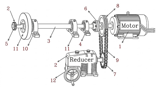
Fig. 1. Architecture of the rotating machinery test bed
2.2 Structural integrity and stress analysis
The shaft was designed using standard torsion and bending formulas [8,9], with the safety criterion:
where τ is shear stress, K the stress concentration factor, and Rpg the allowable shear strength.
Torsional stress verification confirms a high safety margin (Table 1).
Table 1. Torsional stress verification
|
Section diameter d (mm) |
Calculated shear stress τ(N/mm²) |
Safety criterion τ⋅K ≤ Rpg |
Status |
|
25 |
1.612 |
4.35 |
Safe |
|
30 |
0.933 |
2.51 |
Safe |
|
40 |
0.324 |
0.87 |
Safe |
Static equilibrium analysis, illustrated in Figure 2, identified the mid-span (250–450 mm) as the critical section due to the peak load distribution.
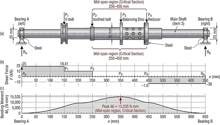
Fig. 2. Internal forces and bending moment distribution along the main shaft
The structural analysis confirms a robust design; with an equivalent bending stress of only 6.67 N/mm² against a yield strength of 355 N/mm², the shaft maintains a substantial safety margin. This ensures that the system remains within the elastic domain during dynamic trials, preventing permanent deformation or fatigue-related failure.
The mid-span region is therefore identified as the critical section, although the calculated stresses remain far below the yield strength, ensuring predominantly elastic behaviour.
2.3 Manufacturing and assembly
2.3.1 High-precision machining
All rotating parts were fabricated using CNC turning and milling to minimize parasitic vibrations [1,3,4]:
- CNC machining: Used to minimize eccentricity and circularity errors.
- Keyway tolerances: Precisely machined for reliable torque transmission and to prevent backlash
2.3.2 Assembly and dynamic neutrality
The assembly procedure incorporated:
- Balancing discs: Used to correct residual unbalance and promote smooth operation.
- Signal integrity: High SNR was targeted so that vibration signals primarily reflected intentional faults rather than parasitic effects [6,7,10].
The measured vibration can be conceptually represented as
Minimizing parasitic vibrations ensures reliable diagnostics.
The equation (2) indicates that the measured vibration is the combined effect of the vibration generated by the fault and unwanted parasitic vibrations or noise from other sources.
2.4 Experimental validation and signal acquisition
To validate the performance of the proposed rotating machinery test bed, a series of controlled vibration measurements was carried out under laboratory conditions. The experimental setup was designed to reproduce representative fault conditions, including rotor imbalance and shaft misalignment, while maintaining repeatable operating conditions. All experiments were performed under continuous operator supervision, and the rotating components were operated within their design limits in accordance with standard laboratory safety procedures.
The vibration signals were acquired using ASH 201 high-sensitivity piezoelectric accelerometers with a nominal sensitivity of 100 mV/g. The accelerometers were mounted on the pillow block bearings using magnetic bases and positioned to measure vibrations in two orthogonal directions (horizontal and vertical). The sensors have a measurement bandwidth of 2 Hz–10 kHz, a resonance frequency above 20 kHz, a measurement range of ±80 g, and an operating temperature range from −20 °C to +120 °C, with the upper limit depending on cable characteristics.
The vibration signals were sampled at 2000 Hz, providing sufficient frequency resolution for detecting the fundamental and harmonic components of machine vibration. The signals were processed using the Fast Fourier Transform (FFT) to identify dominant spectral components and diagnose mechanical faults.
All experimental measurements presented in this study were performed at a constant rotational speed and under a fixed mechanical load. This operating condition was intentionally selected to isolate vibration signatures associated with rotor imbalance and shaft misalignment and to ensure high repeatability of the acquired signals. The influence of varying torque and load conditions on fault signatures is therefore outside the scope of the present experiments and is identified as future work.
3 Results and discussion
3.1 Experimental validation and FFT analysis
Figure 3a presents the FFT spectrum under the faulty condition. A dominant 1X peak at 25 Hz indicates rotor imbalance, while a secondary 2X peak at 50 Hz suggests shaft misalignment. The high amplitude levels indicate a severe machine condition according to the ISO 10816 reference used in this study.
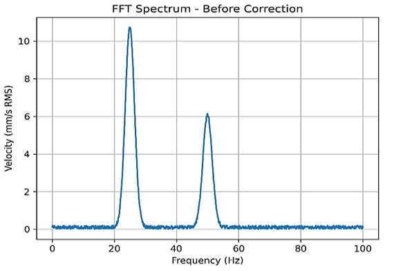
Fig. 3a. Faulty-condition FFT spectrum showing the 1X and 2X components
Figure 3b presents the spectrum after corrective maintenance. The 1X and 2X components are significantly attenuated, demonstrating the effectiveness of balancing and alignment.
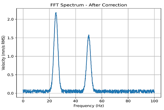
Fig. 3b. FFT spectrum after correction
Figure 3c provides a comparative view before and after maintenance, highlighting the attenuation of the dominant frequency components.
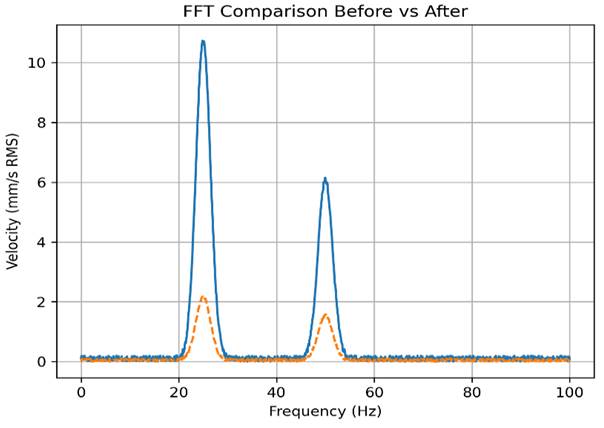
Fig. 3c. Comparative FFT before/after correction
The comparative spectrum clearly highlights the attenuation of vibration energy at the fundamental (1X) and harmonic (2X) frequencies. The results confirm the diagnostic interpretation used in the present controlled experiments:
- 1X → imbalance
- 2X → misalignment
The clear identification and separation of these components demonstrate the sensitivity of the test bed and its ability to reproduce controlled fault signatures.
3.2 Diagnostic performance
Baseline measurements and the corresponding spectrum (Figure 4) revealed:
- 1X (25 Hz): 10.61 mm/s, associated with severe imbalance.
- 2X (50 Hz): 6.0 mm/s, associated with misalignment.
These measurements indicate a severe fault condition according to the ISO 10816 reference [9].

Fig. 4. Initial vibration spectrum
The measured spectra are consistent with the controlled fault scenarios and demonstrate that the precision-machined test bed can produce sufficiently distinct spectral components for diagnostic analysis.
The fundamental frequency is determined from the rotational speed:
f=RPM/60⇒f=1500/60=25 Hz
This provides a reliable operating-frequency baseline for subsequent fault-propagation and maintenance studies.
The interpretation of 1X and 2X is based on the controlled experimental conditions. These components are not, by themselves, unique identifiers of imbalance and misalignment; additional diagnostic information such as phase, axial vibration, and orbit analysis can further improve fault discrimination [1,4,11].
3.3 Optimization and maintenance strategy
To demonstrate the bench's utility as a high-fidelity maintenance research tool, dynamic balancing and laser-assisted alignment were performed [4,8]. Table 2 summarizes the effectiveness of the corrective actions.
Table 2. Vibration level analysis: pre- and post-correction results
|
Peak Component |
Initial (mm/s) |
Post-Correction (mm/s) |
Condition Assessment |
|
1X Peak (Imbalance) |
10.61 |
2.1 |
Good |
|
2X Peak (Misalignment) |
6.00 |
1.5 |
Acceptable |
The overall RMS vibration level reported in this study corresponds to the global vibration velocity measured directly by the vibration analyzer over the entire acquisition interval. This value is used to assess machine condition according to ISO 10816, whereas the FFT spectra present the amplitudes of individual frequency components such as 1X and 2X. Consequently, the overall RMS value should not be interpreted as the arithmetic sum of the spectral peak amplitudes.
As shown in Fig. 5, the comparative FFT spectra clearly illustrate the reduction in vibration amplitudes following the balancing and alignment correction procedures. The reduction of the spectral peaks demonstrates the system's responsiveness to standard industrial maintenance protocols. In particular, the corrective actions reduced the measured 1X component from 10.61 to 2.1 mm/s and the 2X component from 6.00 to 1.5 mm/s. These results confirm the effectiveness of the corrective procedures and support the use of the proposed test bed for condition-monitoring research and controlled maintenance experiments.
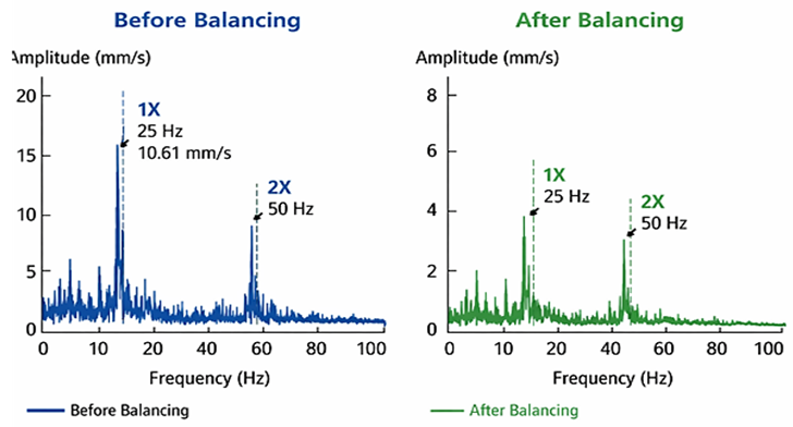
Fig. 5. Comparative FFT analysis illustrating the significant reduction in vibration amplitudes following balancing and alignment correction
3.4 Fault decoupling and AI validation
The test bed was designed to allow controlled introduction of faults on the CNC-machined shaft. This setup enables clear separation of the 1X fundamental and 2X harmonic frequency components, which correspond to rotor imbalance and shaft misalignment, respectively, under the controlled conditions of this study. By isolating these spectral signatures, the system provides high-quality labelled datasets for the development and validation of AI diagnostic models [6,7,10,12].
The primary objective of the present study is the development and experimental validation of the test bench together with the generation of a high-quality labelled vibration dataset, rather than the implementation of a specific artificial intelligence model. The acquired database can nevertheless serve as a benchmark for future machine-learning and deep-learning applications. After signal acquisition and preprocessing, the vibration data can be used for feature extraction or directly processed by data-driven algorithms such as Convolutional Neural Networks (CNNs) and Recurrent Neural Networks (RNNs) for automated fault classification and predictive maintenance.
The main advantages of the proposed test bed compared with the general characteristics reported in recent literature are summarized in Table 3. In particular, the platform provides improved data clarity through precision CNC manufacturing, controlled fault conditions, and distinct spectral signatures. These characteristics facilitate the interpretation of vibration features and provide a more controlled basis for subsequent AI-based diagnostic studies.
Table 3. Comparative advantages of the test bed
|
Feature |
Recent Literature (General) |
Present Study |
|
Data Clarity |
Often "noisy" due to parasitic vibrations [11]. |
High SNR (Signal-to-Noise Ratio) via CNC precision. |
|
Fault Identification |
Overlapping signatures complicate analysis. |
Clear decoupling of 1X and 2X components. |
|
AI Integration |
Focus on purely data-driven models [12]. |
Focus on Physics-Informed validation for AI. |
As highlighted in Table 3, the principal contribution of the proposed platform is not the implementation of a specific AI algorithm but the provision of a controlled and experimentally validated data-generation environment. The structured experimental approach is intended to ensure that vibration signals predominantly reflect intentional faults, thereby reducing noise and ambiguity in the datasets. Consequently, the generated data can support the investigation of correlations between spectral features and fault types and can be used in subsequent AI validation studies.
The controlled environment with clean spectral separation bridges classical rotor dynamics and machine-learning frameworks and provides a useful experimental and educational platform.
It should be emphasized that 1X and 2X frequency components are not unique to rotor imbalance and shaft misalignment. Their interpretation in the present work relies on controlled fault experiments and on the observed reduction of the corresponding spectral peaks after balancing and alignment. Additional diagnostic techniques, such as phase analysis, axial vibration measurements, and orbit analysis, could further improve fault discrimination and will be considered in future developments.
Beyond fault diagnosis, the proposed experimental platform provides a foundation for future predictive-maintenance research. By progressively introducing controlled levels of rotor imbalance, shaft misalignment, bearing degradation, or other mechanical faults, the test bed could generate long-term degradation trajectories and labelled time-series datasets representative of equipment ageing. Such datasets could support the development and validation of prognostic algorithms dedicated to Remaining Useful Life (RUL) estimation. These long-term degradation experiments are beyond the scope of the present study.
3.5 Structural safety and resonance assessment
To further assess the reliability and robustness of the developed rotating machinery test bed, a structural safety and resonance assessment was conducted. The analysis combines experimental vibration measurements with numerical modal modelling to assess the dynamic response under typical operating conditions. The objective is to verify that the test bed remains structurally safe, avoids primary resonance, and provides reliable conditions for fault-reproduction experiments.
3.5.1 Resonance margin evaluation
The nominal operating frequency of the system is defined as:
corresponding to 1500 rpm
From ANSYS modal analysis, the first natural frequency is:
fn1=318.5 Hz
The Resonance Safety Factor (RSF) is calculated as:
RSF=fn1/fserv=318.5/25≈12.74
The first natural frequency is therefore more than 12 times higher than the excitation frequency, indicating that the system operates far from its primary resonance region. The study uses a ratio greater than 1.25 as a practical separation criterion; under this criterion, the test bed is dynamically stable under nominal conditions [8,12].
Figure 6 presents a schematic representation of the resonance margin evaluation based on the experimentally identified operating frequency and the first natural frequency obtained from the finite element modal analysis. It is intended to illustrate the frequency separation rather than to present the complete modal analysis results.
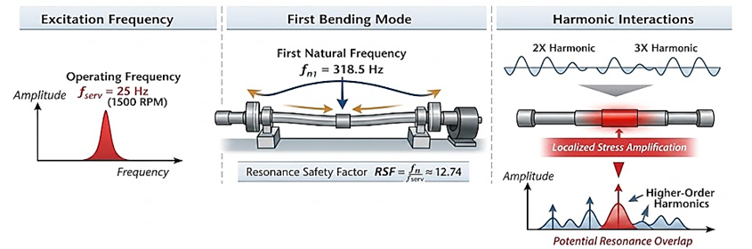
Fig. 6. Schematic showing operating frequency, first bending mode, and harmonic interactions
Although the primary mode is safely separated from the operating frequency, higher-order harmonics generated by imbalance and misalignment can approach local natural frequencies, potentially causing localized stress amplification [8,9,11,12].
Based on the experimental measurements:
- Measured vibration velocity: v=0.021 m/s
- Corresponding angular frequency: ω=2πf=2π×25≈157 rad/s
- Resulting acceleration: a=v⋅ω≈0.021×157≈3.3 m/s2
This local dynamic excitation may increase cyclic stresses in critical shaft regions, emphasizing the importance of monitoring harmonic interactions for long-term fatigue assessment [3,4].
The combination of numerical and experimental data indicates that the test bed is globally safe under the investigated nominal conditions, while localized dynamic effects should nevertheless be considered when designing experiments or validating predictive-maintenance models.
3.5.2 Experimental visual validation
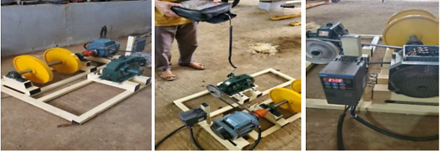
Photographs of the test bench complement the experimental results by illustrating the structural configuration and the dynamic behaviour of the system under nominal operating conditions.
|
a) |
b) |
c) |
Fig. 7. a) Overview of the rotating machinery test bed including the motor, shaft, bearings,and balancing system, b) and c) Test bench running at 25 Hz to show how the rotating parts behave under normal conditions
As shown in Figure 7 a), the modular design allows easy access to all components, facilitating fault introduction and measurement. Figure 7 b) and c) highlights the system behaviour during operation at 25 Hz, confirming stable rotation and the absence of excessive vibration after balancing. These visual observations are consistent with the measured vibration signals and FFT analysis presented earlier.
These observations further validate the reliability and robustness of the proposed test bench, leading to the following conclusions.
The photographs are provided solely to illustrate the experimental setup and the main components of the test bench. They are not intended to demonstrate vibration levels or rotational stability, which are assessed exclusively through the vibration measurements and FFT analysis.
4 Conclusions
This study presented the development and experimental validation of a modular rotating-machinery test bed designed for controlled fault reproduction and condition-monitoring research. The proposed platform combines a robust mechanical architecture, precision CNC manufacturing, and reliable vibration instrumentation, providing a controlled and repeatable environment for investigating rotor imbalance and shaft misalignment, either independently or simultaneously. The modular configuration facilitates the generation of well-defined fault conditions while minimizing geometric imperfections and parasitic vibrations, thereby improving the quality and reproducibility of the acquired vibration signals.
Experimental results demonstrated the effectiveness of the platform for fault identification using FFT-based vibration analysis. Under the investigated operating conditions, the rotational frequency of 25 Hz was clearly identified as the 1X component associated with rotor imbalance, while the 50 Hz component (2X) was associated with shaft misalignment. Following corrective actions, the vibration amplitude associated with imbalance decreased from 10.61 to 2.1 mm/s, whereas the misalignment-related component decreased from 6.00 to 1.5 mm/s. These reductions confirm the effectiveness of dynamic balancing and shaft alignment and demonstrate the capability of the proposed test bed to reproduce, identify, and quantify characteristic fault signatures.
The structural assessment further confirmed the mechanical safety of the platform under the investigated operating conditions. The first natural frequency was determined to be 318.5 Hz, substantially higher than the 25 Hz operating frequency, resulting in a Resonance Safety Factor (RSF) of approximately 12.74. This large frequency separation indicates a low risk of global resonance during normal operation. Nevertheless, higher-order harmonics generated under severe fault conditions may interact with local structural modes; therefore, harmonic monitoring remains important for future fatigue and long-term durability investigations.
Overall, the developed test bed provides a high-fidelity and reproducible experimental platform for rotating-machinery condition monitoring. Its ability to generate controlled and labelled vibration datasets makes it particularly suitable for the development and validation of data-driven and AI-based predictive-maintenance methods. The platform also provides a foundation for future prognostic studies involving progressive levels of imbalance, misalignment, bearing degradation, and other mechanical faults, enabling the generation of degradation trajectories for Remaining Useful Life (RUL) estimation. Although such long-term degradation experiments, variable-load conditions, and complementary measurements such as phase, axial vibration, and orbit analysis are beyond the scope of the present study, they represent natural extensions of the proposed framework. Consequently, the test bed bridges conventional rotor-dynamics experimentation with emerging Industry 4.0 applications, including intelligent condition monitoring, digital twins, and predictive maintenance.
Acknowledgements
The authors gratefully acknowledge the Structural Research Laboratory and the Department of Mechanical Engineering, University of Blida 1, for providing the facilities and technical environment required to conduct the experimental work. The authors also sincerely thank SARL VIBRATECH, Larbaa (Blida), for its valuable assistance in providing the instrumentation required for the experimental measurements.
References
- Randall, R. B. (2011). Vibration-based condition monitoring (2nd ed.). Wiley. https://doi.org/10.1002/9780470977668
- Bently, D. E., & Hatch, C. T. (2002). Fundamentals of rotating machinery diagnostics. ASME Press. https://doi.org/10.1115/1.801FRM
- Jardine, A. K. S., Lin, D., & Banjevic, D. (2006). A review on machinery diagnostics and prognostics implementing condition-based maintenance. Mechanical Systems and Signal Processing, 20(7), 1483–1510. https://doi.org/10.1016/j.ymssp.2005.09.012
- Lei, Y., Li, N., Guo, L., Li, N., Yan, T., & Wang, L. (2018). Machinery health prognostics: A systematic review from data acquisition to RUL prediction. Mechanical Systems and Signal Processing, 104, 799–834. https://doi.org/10.1016/j.ymssp.2017.11.016
- Lee, J., Bagheri, B., & Kao, H. A. (2015). A cyber-physical systems architecture for industry 4.0-based manufacturing systems. Manufacturing Letters, 3, 18–23. https://doi.org/10.1016/j.mfglet.2014.12.001
- Zhang, W., Yang, D., & Wang, H. (2019). Data-driven methods for predictive maintenance of industrial equipment: A survey. IEEE Systems Journal, 13(3), 2213–2227. https://doi.org/10.1109/JSYST.2019.2905565
- Das, O., Das, D. B., & Birant, D. (2023). Machine learning for fault analysis in rotating machinery: A comprehensive review. Heliyon, 9(6), e17584. https://doi.org/10.1016/j.heliyon.2023.e17584
- Glowacz, A. (2021). Fault diagnosis of rotating machines using signal processing and machine learning methods: A review. Sensors, 21(21), 7395. https://doi.org/10.3390/s21217395
- Lei, Y., Yang, B., Jiang, X., Jia, F., Li, N., & Nandi, A. K. (2020). Applications of machine learning to machine fault diagnosis: A review and roadmap. Mechanical Systems and Signal Processing, 138, 106587. https://doi.org/10.1016/j.ymssp.2019.106587
- Davari, N., Veloso, B., Costa, G. A., Pereira, P. M., Ribeiro, R. P., & Gama, J. (2021). A survey on data-driven predictive maintenance for the railway industry. Sensors, 21(17), 5739. https://doi.org/10.3390/s21175739
- Randall, R. B., & Antoni, J. (2011). Rolling element bearing diagnostics—A tutorial. Mechanical Systems and Signal Processing, 25(2), 485–520. https://doi.org/10.1016/j.ymssp.2010.07.017
- Chen, X., Ma, M., Zhao, Z., Zhai, Z., & Mao, Z. (2022). Physics-informed deep neural network for bearing prognosis with multisensory signals. Journal of Dynamics Monitoring and Diagnostics. https://doi.org/10.37965/jdmd.2022.547
Conflict of Interest Statement
The authors declare that there are no conflicts of interest affecting this research.
Author Contributions
Data Availability Statement
All relevant data supporting the findings of this study, including stress calculations and FFT spectral analysis, are included within the article.
Supplementary Materials
There are no supplementary materials to include.