Volume 23 number 3 article 1295 pages 587-596
Received: May 09, 2025 Accepted: Aug 14, 2025 Available Online: Sep 13, 2025 Published: Sep 15, 2025
DOI: 10.5937/jaes0-59385
EVALUATING DESIGN AND MATERIAL EFFECTS ON COMMERCIAL HIP IMPLANT PERFORMANCE USING FINITE ELEMENT ANALYSIS
Abstract
This study presents a comprehensive finite element analysis of commercial hip implants, emphasizing the influence of geometric configurations and material selection on structural performance under static loading. The investigation considered two distinct stem geometry-oval and mixed profiles and evaluated two biomaterials, cobalt-chromium alloy and Ti-6Al-4V alloy, in metal-on-metal configurations. Commercial hip implant models were developed using CREO software and meshed with optimized grid parameters, adhering to ASTM F2996-13 standards for boundary and load conditions. The primary performance metrics analysed included total deformation, von Mises stress, and elastic strain, indicating structural stability and load-bearing capacity. The results revealed that the oval CoCr stem demonstrated superior mechanical characteristics, exhibiting the lowest deformation (0.078 mm), stress (243.24 MPa), and elastic strain (0.00121 mm/mm), underscoring the biomechanical advantage of the optimized geometry combined with stable biomaterials. The findings highlight that implant geometry significantly affects load distribution and stress concentration, with oval geometries promoting more efficient load transfer. Furthermore, the study underscores the critical role of material properties of CoCr alloys, offering enhanced structural integrity over Ti-6Al-4V. Although the current analysis omits wear, micromotion effects, and surface coating influences, the results lay a foundation for future dynamic loading models for wear analysis and coating strategies. Integrating these parameters could further improve implant longevity and patient outcome. Ultimately, this research advances the understanding of design strategies to optimize implant durability, reduce revision rates, and inform future orthopaedic implant innovations.
Keywords
Content
1 Introduction
The human hip joint, comprising the pelvis, acetabulum, and femoral head, is shown in Figure 1, and plays a critical role in load transmission and mobility. Hip joint damage can result from conditions such as rheumatoid arthritis, osteoporosis, traumatic fractures or accidents [1][2]. This often leads to chronic pain, reduced mobility, and permanent disability [3]. The femoral neck and acetabular region are the most common sites of hip fracture.
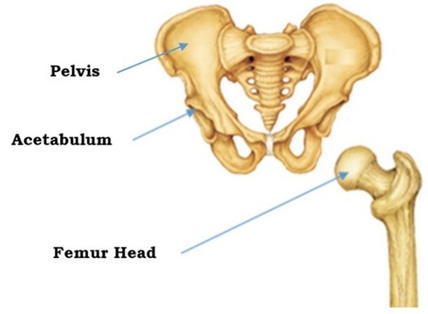
Fig. 1. Structure of Pelvis and Femur [4]
In such scenarios, total hip replacement (THR) has become the standard clinical intervention to restore joint mechanics, alleviate pain, and improve mobility [5]. However, the long-term success of THR is often compromised by implant-related complications including wear-induced osteolysis, aseptic loosening, and biomechanical incompatibility with the host tissue [3].
As illustrated in figure 2, a typical hip implant comprises key components, such as the stem, femoral head, acetabular cup, and backing cup [6]. These components work together to restore the joint function and stability. The choice between partial and THR procedures is determined based on the patient’s clinical condition, extent of joint damage and functional requirements [7][8].
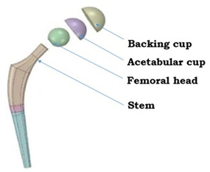
Fig. 2. Exploded full hip implant model [9]
Understanding the causes of hip implant failure is essential for improving implant design and surgical outcomes. The reasons for failure are broadly categorized into five primary groups: aseptic loosening, infection, component failure, periprosthetic fracture, and persistent pain [10] as illustrated in Figure 3. In addition to these clinical complications, implant-related issues such as osteointegration, porous coating delamination, load bearing components wear, periprosthetic fractures due to mechanical mismatch and manufacturing defects have also been identified as contributing factors to implant failure [11][12].
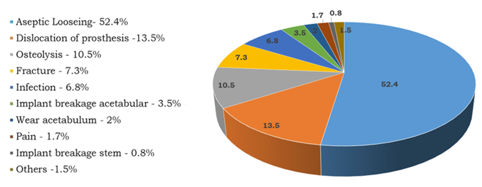
Fig. 3. Statistics on the causes of hip implant failure [13]
Failure in hip implants is predominantly influenced by the femoral stem geometry, material selection, and tribological characteristics of articulating surfaces [14]. Improving implant performance requires a multifactorial approach that combines geometric optimization with the application of advanced biomaterials [15]. A review of the literature reveals a gap in studies that comprehensively integrate stem design, biomaterial properties, and surface-coating strategies to reduce wear, enhance osseointegration, and improve fatigue life [16][17][18].
Figure 4 illustrates the structural performance analysis of commercially relevant femoral stem geometries, specifically, oval and mixed profile models, using finite element analysis (FEA) [13]. The mixed-profile stem model integrates design features from circular, rectangular, and oval geometries, characterized by a straight upper stem, an anterior curvature at the lower section with a defined collar, and a blended transition at the stem base [19].
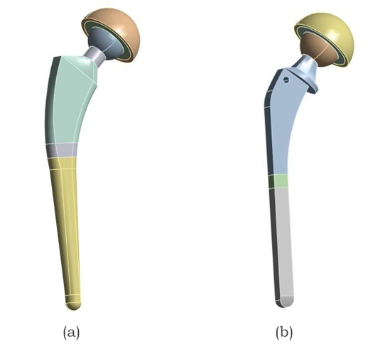
Fig. 4. Two different commercial hip implant models with varying stem geometries, (a) Oval Stem and (b) Mixed profile stem Implant
The mechanical behavior of commonly employed biomaterials, namely, CoCr alloy and Ti-6Al-4V alloy, was evaluated in configurations incorporating metal-on-metal (MoM) [20][21][22], as listed in Table 1.
Table 1. Various material combinations (MC) of hip implant assembly [23]
| Material Combination | Stem shape | Stem | Head | Acetabular Liner | Backing cup |
| MC 1 | Oval | CoCr | CoCr | CoCr | CoCr |
| MC 2 | Ti–6Al–4V | ||||
| MC 3 | Mixed Profile | CoCr | |||
| MC 4 | Ti–6Al–4V |
The primary objective of this study was to establish a computationally driven framework for understanding the static structural behavior under standardized loading conditions, serving as a precursor to the study of implant components under dynamic loading conditions and future coating treatments [6]. Key performance metrics, such as total deformation, von Mises stress, and elastic strain, were extracted to determine the structural stability and load-bearing efficiency across different configurations.
2 Materials & methods
Two commercial stem geometry-oval and mixed profiles were selected based on the National Joint Registry-NJR 21st Annual Report 2024 and their anatomical compatibility with the proximal femur [24]. Figure 5 illustrates 2D drawings of various hip implants based on the specifications provided by reputed manufacturers [25]. Accurate 3-dimensional models of the implants were developed using CREO 11.0, incorporating critical design features such as collars and lateral curvatures of the stem [26].
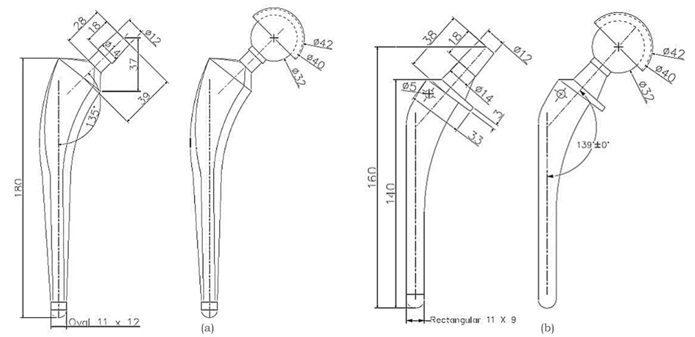
Fig. 5. Detailed drawing of the hip stem and assembled hip implant, (a) Oval stem Implant and (b) Mixed profile stem implant [25] (All dimensions are in mm)
The selected materials were assumed to be homogeneous and to exhibit linear elastic behavior, ensuring consistent mechanical performance across implant components. Material selection was guided by a combination of mechanical strength, biocompatibility, and clinical durability, based on established literature and commercially available data[27][28]. CoCr alloy and Ti–6Al–4V were selected because of their well-established use in orthopedic applications [29]. CoCr exhibits one of the highest elastic moduli among commonly used arthroplasty materials, along with excellent wear resistance and high ultimate tensile strength, making it ideal for load-bearing implants [17][27]. Ti-6Al-4V, on the other hand, offers a favorable balance between low density, high tensile strength, and exceptional corrosion resistance [30]. The mechanical properties of both materials, including the Young’s modulus, density, Poisson’s ratio, and ultimate tensile strength, are listed in Table 2 [31][32][33][23].
Table 2. Materials used and properties for stems
| Sl No | Materials | Young's modulus [GPa] | Density [Kg/m3] | Poisson's ratio | Ultimate Tensile strength [MPa] |
| 1. | Ti–6Al–4V | 114 | 4500 | 0.31 | 930 |
| 2. | CoCr Alloy | 200 | 8500 | 0.30 | 1503 |
The FEA was conducted using ANSYS 2023 R2. An quadratic mesh was adopted to ensure optimal accuracy and computational efficiency [23][34]. A mesh sensitivity analysis was performed on the hip implant model using material configuration MC1 by testing multiple mesh sizes, which initially exhibited significant variations in the output values. However, beyond a mesh size of 1 mm, the result variations became negligible, indicating numerical convergence; thus, a 1 mm mesh size was finalized for subsequent analyses [35]. This validates the fact that the simulations achieved mesh independence, as illustrated in Figure 6.
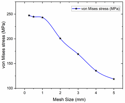
Fig. 6. Grid Independence Analysis performed on the hip implant model using material configuration MC1 by evaluating multiple mesh sizes
A finer mesh comprising hexahedral elements generally provides more accurate results; however, it substantially increases computational time and resource consumption [35]. For illustration purposes, the node and element count for the MC1 and MC2 material configurations are presented in Table 3.
Table 3. Mesh statistics for full hip implant assembly
| Sl No | Hip Implant Assembly | Number of Nodes | Number of Elements |
| 1. | Oval | 8,76,619 | 5,83,649 |
| 2. | Mixed Profile | 9,59,760 | 6,64,273 |
The complete hip implant and mesh model are shown in Figure 7. The boundary and load conditions were applied according to ASTM F2996-13 [36]. In this simulation, the load was imposed at the top center of the acetabular cup.
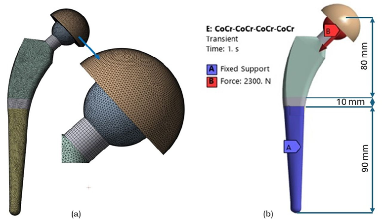
Fig. 7. (a) Meshed FEM of the complete hip implant assembly, illustrating the integration of stem, femoral head and acetabular cup components. (b) Boundary conditions on hip implant as per the ASTM F2996-13 standards
As per ASTM standards, the hip implant was segmented into three regions along its total length, beginning from the top center surface of the femoral head, which measured 80 mm. The next incision was made 10 mm below the first. The bottom portion of the stem was confined to all surfaces distal to the second portion of the stem. This fixation method ensures that peak stresses are not introduced in the constrained regions. A static analysis was performed for designs with the same boundary conditions [37].
In this FEA study, which primarily focusing on total deformation, von Mises stress, and elastic strain, serve as critical indicators and widely recognized for evaluating structural performance and stability of hip implants under static loads. The focus on these three parameters provides a comprehensive view of the implant's mechanical response in a static context. While their individual values vary depending on material properties, geometric configurations, and boundary conditions, the study maintains consistent loading scenarios across models to enable direct comparison. Utilizing well-established metrics enhances robustness, as they are validated indicators of mechanical performance.
3 Results and discission
The static structural analysis began with a comparison between oval and mixed-profile femoral stem geometries made of CoCr and Ti–6Al–4V alloys under simulated walking conditions, as shown in Table 4.
Table 4. Structural analysis outcomes of CoCr alloy and Ti-6Al-4V alloy hip stem
| Sl. No | Stem Material | Stem shape | Total deformation in [mm] | Equivalent von Mises stress in [MPa] | Equivalent strain in [mm/mm] |
| 1. | CoCr alloy | Oval | 0.069 | 316.85 | 0.00158 |
| 2. | Mixed Profile | 0.553 | 955.58 | 0.00486 | |
| 3. | Ti–6Al–4V | Oval | 0.126 | 311.48 | 0.00283 |
| 4. | Mixed Profile | 0.969 | 950.43 | 0.00848 |
The CoCr Oval stem exhibited the lowest total deformation (0.069 mm), reduced von Mises stress (316.85 MPa), and lowest elastic strain (0.00158 mm/mm). In contrast, the Ti–6Al–4V Mixed stem showed the highest deformation (0.969 mm) and stress (950.43 MPa), indicating inferior load-bearing performance.
Building upon these initial findings, a comprehensive full hip implant analysis was conducted to further evaluate the four MoM articulation frameworks, as mentioned in Table 1, to investigate the influence of geometry and material on overall implant performance. Table 5 summarizes the simulation outcomes for the four hip implant configurations.
Table 5. Structural analysis results for hip implants with various configuration
| Material Combination | Stem shape | Total deformation in [mm] | Equivalent von Mises stress in [MPa] | Equivalent strain in [mm/mm] |
| MC 1 | Oval | 0.078 | 243.24 | 0.0012 |
| MC 2 | 0.141 | 233.05 | 0.0021 | |
| MC 3 | Mixed profile | 0.663 | 954.43 | 0.0049 |
| MC 4 | 1.161 | 949.32 | 0.0085 |
When evaluated in full assembly, the oval CoCr stem with the MoM configuration yielded the most favorable outcome across all models, with the lowest deformation (0.078 mm), stress (243.24 MPa), and elastic strain (0.00121 mm/mm). Figure 8 illustrates the mixed profile Ti-6Al-4V stem with higher deformation (1.161 mm) and stress values (949.32 MPa).
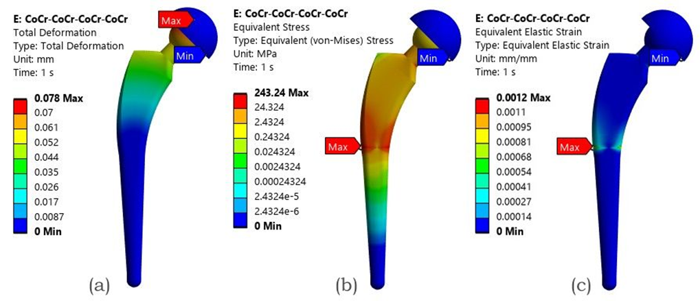
Fig. 8. FEA result of the MoM configuration with an Oval CoCr stem - (a) Total deformation, (b) von Mises stress (c) Elastic strain
3.1 Discussion
The simulation results revealed that implant geometry and material selection play a pivotal role in determining the mechanical performance of THR under structural static loads [38]. In alignment with the findings from our previously published study, the oval stem demonstrated the most favorable mechanical response, followed closely by the rectangular stem. These configurations outperformed circular and mixed-profile stems in terms of reduced total deformation, lower von Mises stress, and equivalent strain, indicating an enhanced structural efficiency under simulated loading conditions [19]. Among the materials assessed, CoCr alloys demonstrated lower deformation and stress, exhibiting superior mechanical strength and higher wear and corrosion resistance than Ti-6Al-4V alloys, making them more suitable for high-load-bearing orthopedic applications [39].
The oval CoCr stem with the MoM articulation exhibited the lowest deformation (0.078 mm) and stress (243.24 MPa). In contrast, the Ti-6Al-4V stems showed higher stress values exceeding (954.43 MPa) and deformation above (0.663 mm). Table 6 presents the simulated results in direct comparison with relevant literature findings, highlighting the percentage variations in the outcomes and validating the consistency and reliability of the current static analysis.
Table 6. Comparative validation of FEA results with existing literature data
| Sl. No | Material Combination | Key Parameters | Current Study | Literature Study | Percentage Variations % | References |
| 1. | MoM with CoCr alloy Oval Stem | Total deformation in mm | 0.078 | 0.1036 | 24.71 | [9] |
| 2. | Equivalent von Mises stress in MPa | 243.24 | 217.97 | 11.59 | ||
| 3. | Equivalent strain in mm/mm | 0.0012 | 0.0035 | 65.71 | ||
| 4. | MoM with Ti6Al4V alloy Mixed profile Stem | Total deformation in mm | 0.663 | 0.456 | 45.39 | [40] |
| 5. | Equivalent von Mises stress in MPa | 954.43 | 709.64 | 34.49 | ||
| 6. | Equivalent strain in mm/mm | 0.0049 | 0.00692 | 29.19 |
These outcomes align with previous studies indicating that CoCr alloys, owing to their higher Young’s modulus and ultimate tensile strength, offer superior stiffness and load-bearing capacity compared with Ti-6Al-4V alloys [39].
From a design perspective, these results underscore the mechanical advantages of pairing CoCr alloys with anatomically adaptive geometries, particularly oval stems. Such configurations not only reduce the risk of mechanical failure but also minimize micromotion, which contributes to aseptic loosening [41]. Although MoM articulations exhibit superior mechanical stability and reduced wear, the associated release of numerous nanosized wear particles and metal ions raises biological concerns, underscoring the need to evaluate alternative articulations involving polymers, ceramics and composite materials [42][43][44]. Additionally, this study validates the relevance of FEA as a predictive tool for preclinical evaluation and informs future directions for optimizing implant coatings.
Overall, this study highlights the importance of integrating material, geometry, and articulation choices into a unified design strategy. These insights can guide orthopedic surgeons and manufacturers in selecting configurations that maximize implant longevity and performance, while minimizing revision rates. The findings also establish a baseline for future studies incorporating dynamic loading in wear analysis and coating thickness optimization to further enhance the implant reliability of load-bearing hip implant components.
3.1.1 Application
The obtained results from this computational study—hold direct applicability in clinical and industrial practice [45]. For example, identifying that an oval CoCr stem in a MoM configuration exhibits favorable stress transfer and reduced micromotion can be helpful to orthopedic surgeons during implant selection, particularly for active or high-demand patients who require enhanced mechanical stability [46]. These findings can also guide implant manufacturers in optimizing taper design and material pairing to improve longevity and reduce the risk of wear-induced complications such as fretting corrosion or aseptic loosening.
Furthermore, the validated FEA approach can be integrated into preclinical testing to simulate performance under patient-specific loading conditions, reducing reliance on costly physical prototypes [47][48]. In regulatory practice, such computational evidence can support device approvals by demonstrating safety and efficacy under worst-case scenarios aligned with ASTM standards [37]. Thus, the results not only contribute to fundamental understanding but also support tangible improvements in implant design, surgical planning, and post-operative outcomes.
3.1.2 Limitations and future scope
This study acknowledges certain limitations. The current static analysis does not account for micromotion effects, wear simulations, or the impact of advanced surface coatings and treatments. Although finite element methods (FEM) offer a time-efficient approach for evaluating medical implants, they are associated with challenges such as modeling complexity and handling material and geometric nonlinearities.
The material properties used in this analysis were derived from validated literature sources and standardized data sheets. While experimental determination of these properties could add further accuracy, it lies outside the scope of this investigation. Additionally, experimental validation using 3D-printed prototypes and hip simulator testing is planned to verify the FEM-based findings.
Future research should focus on overcoming these limitations by integrating dynamic loading conditions, analyzing the long-term effects of wear and coating performance, and developing patient-specific implant designs. Such advancements would contribute to enhanced reliability, durability, and clinical success of hip implant systems.
4 Conclusion
This study established that the implant geometry and material composition critically influence the mechanical performance of hip prostheses under structural static loading. Among all evaluated configurations, the oval stem made from the CoCr alloy in a MoM configuration demonstrated the most favorable mechanical characteristics, exhibiting the lowest total deformation (0.078 mm), von Mises stress (243.24 MPa), and equivalent strain (0.00121 mm/mm). These findings underscore the mechanical advantages of CoCr alloys relative to Ti-6Al-4V, particularly when combined with oval or rectangular stem geometries that promote efficient load distribution. Future validation using these models will not only improve the accuracy of simulation-based predictions, but also serve as a practical framework for advancing implant design standards.
Acknowledgements
This study received no external funding. The authors would like to thank the Department of Aeronautical and Automobile Engineering, Manipal Institute of Technology, Manipal Academy, Manipal, for the computing resources provided to carry out this research.
References
- G.S. Man, G. Mologhianu, Osteoarthritis pathogenesis - a complex process that involves the entire joint., J. Med. Life 7 (2014) 37–41.
- Q. Guo, Y. Wang, D. Xu, J. Nossent, N.J. Pavlos, J. Xu, Rheumatoid arthritis: Pathological mechanisms and modern pharmacologic therapies, Bone Res. 6 (2018). https://doi.org/10.1038/s41413-018-0016-9.
- P. Fardellone, E. Salawati, L. Le Monnier, V. Goëb, Bone loss, osteoporosis, and fractures in patients with rheumatoid arthritis: A review, J. Clin. Med. 9 (2020) 1–18. https://doi.org/10.3390/jcm9103361.
- D. Soloviev, L. Maslov, M. Zhmaylo, Acetabular Implant Finite Element Simulation with Customised Estimate of Bone Properties, Materials (Basel). 16 (2023). https://doi.org/10.3390/ma16010398.
- S. Affatato, A. Ruggiero, M. Merola, Advanced biomaterials in hip joint arthroplasty. A review on polymer and ceramics composites as alternative bearings, Compos. Part B Eng. 83 (2015) 276–283. https://doi.org/10.1016/j.compositesb.2015.07.019.
- M.L.M. Daniela Milagros Anticona, Jose Luis Serna Landivar, William Algoner, Static, Transient, and Fatigue Design and Analysis of a Hip Femoral Stem Using the Finite Element Method., (n.d.).
- A. Jahnke, T. Harz, C.A. Fonseca Ulloa, B.A. Ishaque, M. Rickert, Development and Finite Element (FE) analysis of a novel short hip stem concept, J. Orthop. 46 (2023) 117–123. https://doi.org/10.1016/j.jor.2023.09.016.
- S.M. Darwish, A.M. Al-Samhan, Optimization of artificial hip joint parameters, Materwiss. Werksttech. 40 (2009) 218–223. https://doi.org/10.1002/mawe.200900430.
- A.K. Bhawe, K.M. Shah, S. Somani, S. Shenoy B, S. Bhat N, M. Zuber, Chethan, Static structural analysis of the effect of change in femoral head sizes used in Total Hip Arthroplasty using finite element method, Cogent Eng. 9 (2022). https://doi.org/10.1080/23311916.2022.2027080.
- U. Anil, V. Singh, R. Schwarzkopf, Diagnosis and Detection of Subtle Aseptic Loosening in Total Hip Arthroplasty, J. Arthroplasty 37 (2022) 1494–1500. https://doi.org/10.1016/j.arth.2022.02.060.
- C. Delaunay, I. Petit, I.D. Learmonth, P. Oger, P.A. Vendittoli, Metal-on-metal bearings total hip arthroplasty: The cobalt and chromium ions release concern, Orthop. Traumatol. Surg. Res. 96 (2010) 894–904. https://doi.org/10.1016/j.otsr.2010.05.008.
- F. Schönweger, C.M. Sprecher, S. Milz, C. Dommann-Scherrer, C. Meier, A. Dommann, A. Neels, P. Wahl, New insights into osteointegration and delamination from a multidisciplinary investigation of a failed hydroxyapatite-coated hip joint replacement, Materials (Basel). 13 (2020) 1–17. https://doi.org/10.3390/ma13214713.
- Chethan, S. Bhat N, M. Zuber, S. Shenoy B, Evolution of different designs and wear studies in total hip prosthesis using finite element analysis: A review, Cogent Eng. 9 (2022). https://doi.org/10.1080/23311916.2022.2027081.
- T. Hidayat, M.I. Ammarullah, E. Saputra, M.D.P. Lamura, C. K N, R. Ismail, A.P. Bayuseno, J. Jamari, A method for estimating the contact area of a dual-mobility total hip prosthesis, AIP Adv. 14 (2024). https://doi.org/10.1063/5.0188638.
- L. Guo, S. Ataollah Naghavi, Z. Wang, S. Nath Varma, Z. Han, Z. Yao, L. Wang, L. Wang, C. Liu, On the design evolution of hip implants: A review, Mater. Des. 216 (2022). https://doi.org/10.1016/j.matdes.2022.110552.
- E. Celik, F. Alemdar, M. Bati, M.F. Dasdemir, O.A. Buyukbayraktar, K.N. Chethan, M. Kara, S. Mihcin, Mechanical Investigation for the Use of Polylactic Acid in Total Hip Arthroplasty Using FEM Analysis, Lect. Notes Networks Syst. 328 LNNS (2022) 17–23.
- M.A. Hussein, A.S. Mohammed, N. Al-Aqeeli, Wear characteristics of metallic biomaterials: A review, Materials (Basel). 8 (2015) 2749–2768. https://doi.org/10.3390/ma8052749.
- S. Mischler, A.I. Muñoz, Wear of CoCrMo alloys used in metal-on-metal hip joints: A tribocorrosion appraisal, Wear 297 (2013) 1081–1094. https://doi.org/10.1016/j.wear.2012.11.061.
- O.S. Paper, A. Engineering, Computational analysis of hip prosthesis: impact of shape and material on mechanical performance 1, (2025).
- T. Smoljanic, S. Sedmak, A. Milovanovic, L. Milovic, Numerical simulation of fatigue crack growth in Ti-Al6-V4 hip implants under different exploitation conditions, Procedia Struct. Integr. 48 (2023) 215–221. https://doi.org/10.1016/j.prostr.2023.07.151.
- C.Y. Hu, T.R. Yoon, Recent updates for biomaterials used in total hip arthroplasty, Biomater. Res. 22 (2018) 1–12. https://doi.org/10.1186/s40824-018-0144-8.
- J.V. Corda, K.N. Chethan, B. Satish Shenoy, S. Shetty, N. Shyamasunder Bhat, M. Zuber, Fatigue Life Evaluation of Different Hip Implant Designs Using Finite Element Analysis, J. Appl. Eng. Sci. 21 (2023) 896–907. https://doi.org/10.5937/jaes0-44094.
- J.V. Corda, C. K N, S. Bhat N, S. Shetty, S. Shenoy B, M. Zuber, Finite element analysis of elliptical shaped stem profile of hip prosthesis using dynamic loading conditions, Biomed. Phys. & Eng. Express 9 (2023) 65028. https://doi.org/10.1088/2057-1976/acfe14.
- M. Wilkinson, S. Dawson-bowling, A. Goldberg, A. Porteous, A. Watts, E. Young, V. Mccormack, M. Swanson, A. Blom, 21st National Joint Registry Annual Report, (2024).
- DePuy Synthes, CORAILTM Total Hip System – Surgical Technique. Johnson & Johnson Medical Ltd, DePuy Synth. (2022). https://www.depuysynthes.com (accessed November 12, 2024).
- N. Nikam, S. Shenoy, L. Keni, S. Shetty, S. Bhat, K.N. Chethan, Computational analysis of hip prosthesis: Impact of shape and material on mechanical performance, J. Appl. Eng. Sci. 23 (2025) 314–321. https://doi.org/10.5937/jaes0-55883.
- N. Nikam, S. Shenoy B, C. K N, L.G. Keni, S. Shetty, S. Bhat N, Advancements in Surface Coatings for Enhancing Longevity in Hip Implants: A Review, Prosthesis 7 (2025) 1–28. https://doi.org/10.3390/prosthesis7010021.
- A. Sedmak, K. Čolić, Fracture and fatigue behaviour of implants made of Ti alloys, Procedia Struct. Integr. 23 (2019) 45–50. https://doi.org/10.1016/j.prostr.2020.01.061.
- A.Z. Senalp, O. Kayabasi, H. Kurtaran, Static, dynamic and fatigue behavior of newly designed stem shapes for hip prosthesis using finite element analysis, Mater. Des. 28 (2007) 1577–1583. https://doi.org/10.1016/j.matdes.2006.02.015.
- C.A. Buckner, R.M. Lafrenie, J.A. Dénommée, Biomaterials in Total Joint Arthroplasty, Intech 11 (2016) 13.
- J. Reginald, M. Kalayarasan, K.N. Chethan, P. Dhanabal, Static, dynamic, and fatigue life investigation of a hip prosthesis for walking gait using finite element analysis, Int. J. Model. Simul. 43 (2023) 797–811. https://doi.org/10.1080/02286203.2023.2212346.
- H. Göktaş, E. Subaşi, M. Uzkut, M. Kara, H. Biçici, H. Shirazi, K.N. Chethan, Ş. Mihçin, Optimization of Hip Implant Designs Based on Its Mechanical Behaviour, Lect. Notes Networks Syst. 328 LNNS (2022) 37–43. https://doi.org/10.1007/978-3-030-86297-8_4.
- A. Aherwar, A. K Singh, A. Patnaik, Current and future biocompatibility aspects of biomaterials for hip prosthesis, AIMS Bioeng. 3 (2015) 23–43. https://doi.org/10.3934/bioeng.2016.1.23.
- Ikhsan, J. Triyono, A.R. Prabowo, J.M. Sohn, Investigation of meshing strategy on mechanical behaviour of hip stem implant design using FEA, Open Eng. 10 (2020) 769–775. https://doi.org/10.1515/eng-2020-0087.
- A.T. Alpkaya, S. Mihcin, Sensitivity Analysis of Wear on Metal-On-Metal Bearing Couples via Verification of Numeric and Analytic Methods, Hittite J. Sci. Eng. 11 (2024) 57–67. https://doi.org/10.17350/hjse19030000332.
- ASTM, F 2996-20 Standard Practice for Finite Element Analysis ( FEA ) of Non-Modular Metallic Orthopaedic Hip Femoral Stems, ASTM Int. Conshohocken, PA, Www.Astm.Org (2020) 1–11. https://doi.org/10.1520/F2996-13.2.
- S. Karimi, F. Haji Aboutalebi, M. Heidari-Rarani, A numerical study on fatigue design of Ti-6Al-4V total hip stem: infinite-life and damage tolerance approaches using XFEMPN-VCCT, Meccanica 58 (2023) 959–980. https://doi.org/10.1007/s11012-023-01661-6.
- N. Kladovasilakis, K. Tsongas, D. Tzetzis, Finite Element Analysis of Orthopedic Hip Implant with Functionally Graded Bioinspired Lattice Structures, Biomimetics 2020, Vol. 5, Page 44 5 (2020) 44. https://doi.org/10.3390/BIOMIMETICS5030044.
- C. K.N., M. Zuber, S. Bhat N., S. Shenoy B., C. R. Kini, Static structural analysis of different stem designs used in total hip arthroplasty using finite element method, Heliyon 5 (2019) e01767. https://doi.org/10.1016/j.heliyon.2019.e01767.
- T. Joshi, R. Sharma, V. Kumar Mittal, V. Gupta, Comparative investigation and analysis of hip prosthesis for different bio-compatible alloys, Mater. Today Proc. 43 (2020) 105–111. https://doi.org/10.1016/j.matpr.2020.11.222.
- G. Matsoukas, I.Y. Kim, Design optimization of a total hip prosthesis for wear reduction, J. Biomech. Eng. 131 (2009) 1–12. https://doi.org/10.1115/1.3049862.
- S. Suñer, J.L. Tipper, N. Emami, Biological effects of wear particles generated in total joint replacements: Trends and future prospects, Tribol. - Mater. Surfaces Interfaces 6 (2012) 39–52. https://doi.org/10.1179/1751584X12Y.05.
- O.M. Posada, R.J. Tate, M.H. Grant, Effects of CoCr metal wear debris generated from metal-on-metal hip implants and Co ions on human monocyte-like U937 cells, Toxicol. Vitr. 29 (2015) 271–280. https://doi.org/10.1016/j.tiv.2014.11.006.
- P.J. Firkins, J.L. Tipper, M.R. Saadatzadeh, E. Ingham, M.H. Stone, R. Farrar, J. Fisher, Quantitative analysis of wear and wear debris from metal-on-metal hip prostheses tested in a physiological hip joint simulator., Biomed. Mater. Eng. 11 (2001) 143–157. https://doi.org/142.
- T. Bitter, I. Khan, T. Marriott, E. Lovelady, N. Verdonschot, D. Janssen, The effects of manufacturing tolerances and assembly force on the volumetric wear at the taper junction in modular total hip arthroplasty, Comput. Methods Biomech. Biomed. Engin. 22 (2019) 1061–1072. https://doi.org/10.1080/10255842.2019.1627524.
- C. Simoneau, P. Terriault, B. Jetté, M. Dumas, V. Brailovski, Development of a porous metallic femoral stem: Design, manufacturing, simulation and mechanical testing, Mater. Des. 114 (2017) 546–556. https://doi.org/10.1016/j.matdes.2016.10.064.
- S. Torabnia, S. Mihcin, I. Lazoglu, Design and manufacturing of a hip joint motion simulator with a novel modular design approach, Int. J. Interact. Des. Manuf. 18 (2024) 401–417. https://doi.org/10.1007/s12008-023-01506-2.
- J.G. Bowsher, J.C. Shelton, A hip simulator study of the influence of patient activity level on the wear of crosslinked polyethylene under smooth and roughened femoral conditions, Wear 250–251 (2001) 167–179. https://doi.org/10.1016/S0043-1648(01)00619-6.
Conflict of Interest Statement
The authors declare no conflicts of interest.
Author Contributions
Data Availability Statement
All data generated or analyzed during this study are included in this published article.
Supplementary Materials
There are no supplementary materials to include.