Volume 24 article 1354 pages: 569-581
Received: Mar 28, 2026 Accepted: Jul 15, 2026 Available Online: Aug 03, 2026 Published: Aug 17, 2026
DOI: 10.5937/jaes0-66104
EXPERIMENTAL INVESTIGATION OF THERMAL ENERGY STORAGE PERFORMANCE USING SAND–SOIL MIXTURES IN A HYBRID SOLAR THERMAL SYSTEM
Abstract
The high cost and intermittency of conventional thermal-energy-storage materials limit the wider adoption of solar-assisted cooling for photovoltaic (PV) panels, particularly in hot climates such as Iraq, where excessive panel temperature reduces electrical output. This study experimentally examines whether a low-cost, locally available sand-soil storage medium, combined with a helical-coil heat exchanger operating on a passive thermosiphon principle, can simultaneously cool a PV panel and store thermal energy for later use. A cylindrical storage tank (25 cm diameter, 60 cm height) housing a copper helical coil was placed beneath a solar collector, with a 50/50 water-vegetable-oil mixture circulating as the heat-transfer fluid. Three storage media, pure sand, pure soil, and a sand-soil mixture, were tested under natural and forced convection at mass flow rates of 0.008 and 0.016 kg/s and solar irradiance up to 1000 W/m². The sand-soil mixture consistently outperformed the single-component media, achieving a thermal-storage efficiency of 77% and reducing the solar-cell temperature by approximately 37.5% under natural convection, corresponding to a 39.44% improvement in thermal-energy-storage performance relative to pure sand. These results demonstrate that an inexpensive sand-soil composite can deliver PV cooling and thermal storage performance competitive with more costly engineered storage materials, offering a practical, low-cost pathway to improving the efficiency of solar power systems in hot, arid regions.
Highlights
- A helical-coil heat exchanger operating on natural thermosiphon flow reduced the PV panel temperature by 37.5% under natural convection thermal.
- A sand-soil storage mixture increased thermal-energy-storage performance by 39.44% relative to pure sand.
- A 50/50 water-oil heat-transfer fluid combined with the sand-soil medium achieved a peak thermal-storage efficiency of 77% during discharge.
Keywords
Content
1 Introduction
Solar energy is one of the most essential renewable energy sources due to its abundance and availability. Its applications are broadly classified into two types: thermal uses and photovoltaic (PV) electricity generation. This leads to a hybrid photovoltaic-thermal (PVT) system by combining these applications. In these systems, solar panels generate electricity while a heat exchanger, often using a flowing stream of water, captures thermal energy. The purpose of this integration is twofold, to cool the PV cells so that losses in efficiency of these cells are avoided because of high heating by solar, and to produce useful hot water or higher temperature fluid. The heat transfer studies of the systems, e.g. horizontal ground heat exchanger (GHE) positioning in the forms of slinky or coils are complex, yet required. It is necessary to determine the temperature changes and heat fluxes in soils of a GSHP system to correctly size up of such systems. The ability of the soil to thermally regenerate during the non-use of the heat exchangers can be considered as one of the primary considerations, in this case. A thorough study with accuracy measurements has indicated that the use of antifreeze solutions of high concentrations in the heat transfer liquids is harmful to the heat flux expelled into the ground [1] In design of heat exchanger (e.g. tube-in-tube (or tube-and-cased) types), the most popular methods of analysis are the Log Mean Temperature Difference (LMTD) and effectiveness-NTU methods. Of the most importance among them is the methods that enable putting performance table and characteristic diagrams with dimensionless parameters, which are very helpful in both the design and analysis. The ε-NTU relationships can be obtained by dividing this heat exchanger along the flowing fluid path [2]. The results of a study focused on a photovoltaic-thermal (PVT) system equipped with a geothermal heat exchanger (GHE) employing volcanic tuff as the thermal store showed significant improvements. Such integration yielded up to 23% thermal cooling of solar cell temperature, 4% enhancement in electrical efficiency and 6.56% improvement in power generation as compared to a nominal PVT setup. Also extracted a significant increase in thermal efficiency reaching 70.60%, up from 58.66%. Moreover, the GHE increased exhaust air temperature by 10°C and outperformed receiving ambient air at GHE end points, demonstrating excellent heat recovery. When used with a fan coil unit, the total heating season energy consumption decreased by 14.81% [3]. A climate specific research study was conducted into a cooling system in which hot water is passed to a copper coil present inside the chiller tank. The largest temperature difference for the hot water observed was 17.8°C in May, with average drops of 12.6°C in April, 12.9°C in May and 8.6°C in June. According to an economic analysis, the cost of extracting heat through this method was around 88% cheaper compared to extracting the same amount of heat with electrical means [4]. A hybrid cooling system using evaporative cooling and conventional air conditioning for livestock housing. In this configuration, air is first cooled via evaporation through wet pads and then further chilled by a particular air conditioner’s evaporator. Such an approach gives more cooling power at less price. The results showed that energy consumption of the compressor was reduced by approximately 23% and COP was increased by 17% compared to a standard air conditioning alone [5]. A great amount of studies are concentrated on GHE performance in normal conditions (inlet temperature > 0°C), while for frozen soil conditions, the research is very scarce. Once a model is validated against experimental and Computational Fluid Dynamic (CFD) data, one study confirmed that frozen soil can improve the heat transfer capacities of an earth ground heat exchangers (GHEs) by 30%. The impact of the frozen inlet temperature on surrounding soil temperature was confined to within a radius of less than 4 m. Over a three-month test, the GHEs demonstrated a constant heat transfer rate of 75–80 W/m to guarantee stable GSHP operation [6]. Results from experiments with a heat-pipe heat exchanger showed it could pre-cool a room by up to (9 °C). The optimal configurations showed 93–140 W/m³, which corresponded to around 25%–33% of the cooling demand in the room. Another solar-powered experiment reduced annual energy consumption by 31% and successfully maintained a target temperature of 5°C. This illustrates considerable opportunities for developing solar energy systems and passive cooling technologies in an integrated manner to avoid grid electricity and many installing hours, while keeping comfort [7]. Bubble injection is found as a promising technique for improving the heat transfer in heat exchangers. Bubble injection at the bottom of a water tank (acting as an evaporator in a refrigeration cycle) through a spiral coil heat exchanger submerged into it and varied airflow rates (3-11 L/min). The optimal airflow rate for maximum heat transfer augmentation was found to be 9 L/min [8]. In a review of GHEs for cooling PV panels, both benefits and challenges were discussed. Next, the technology: These systems can lower panel surface temperatures by 20-25 °C and increase thermal and electrical efficiency 20% each. However, they face challenges from installation complexity and maintenance difficulties as well as variability depending on soil properties. Economic and environmental feasibility was also discussed in the review with reference to future research into improved design [9]. An analysis of a solar-powered hybrid heating and cooling system for temperate climates in Europe. The study was conducted based on energy balances but focused on the influence of some system performance parameters, using a lab setup including an evacuated tube solar collector, single stage ammonia-water absorption chiller and hot water tank (in large scale) [10]. Regarding PV module overheating, a study presented a passive cooling system (extended-fin heat sink) mounted at the rear of (760 mm x 550 mm) 50W panel. It was appeared that the longer the fins, the higher heat dissipation. Proved with a fin diameter increase from 8 to 12 mm, we saw a drastic increase of heat loss, and afterwards linear trend up to 20mm [11]. An experimental solar hot water integrated with a ground-air heat exchanger (GAHE) PV system was conducted in Şanlıurfa, Turkey (a hot-dry climate). Performance was tested with air cooled by GAHE compared to direct ambient air cooling. The results indicated that the electrical efficiency of the integrated system was 9.70% higher than that of the uncooled panel (only 4.30% difference compared with the ambient air) and lowered the average surface temperature by 15°C (compared to 7.96°C)[12]. A closed-loop system composed of parallel thermoelectric units placed above and below PV panels under controlled indoor conditions was used to study the countercurrent cooling mechanism employed by distributed thermoelectric heat sinks. The analysis showed that the devices might not only provide better operational temperature regulation than uncooled systems, but at ideal positions from where they were implemented, these may improve energy efficiency of PV system with more reliable coefficients [13]. An internal finned heat exchanger was optimized using a CFD analysis for efficiency purposes. The average outlet fluid temperature achieved was 75.31 °C at input fluid temperature of 27 °C and solar radiation intensity of 1067 W/m² with around 0.22 m² working area for the combined system of the PV cells and heat exchanger [14]. PV panel degradation in harsh climates is accelerated by two factors, there are two main reasons for this, condensation due to low temperatures at night and efficiency loss due to high temperatures during day. Tests comparing two modules with one standard and another fitted with a ground-based heat exchanger indicated that during daytime, integrated system allowed achieving an 8 °C temperature decrease of the cell, while at night, approximately 3 °C above condensation point was achieved [15]. A two-dimensional model was created in ANSYS Fluent software to analyze the performance of an Earth-Water Horizontal Heat Exchanger (EWHE). It explored how the inlet water temperature, flow velocity, soil thermal conductivity and ground surface temperature influenced the heat transfer rate. Thermal transfer rate and the thermal conductivity parameters were positively correlated, while inversely related to ground surface temperature and heat exchange rate [16]. A study compared the hydrothermal performance of series-flow and parallel-flow vertical ground heat exchangers for cooling by 3D transient finite volume simulations in ANSYS. The reduced temperature of 9.39°C and 9.28°C results by the two configurations, respectively, provided a cooling efficiency of improvement of cold water before entering the traditional cooling tower system about 18.31% and 17.73%. Borehole heat exchanger of U-shape: maximum heat extraction rate of 5.21 kW and temperature drop of 5.23°C per well [17]. Soil moisture content (saturation) has a major impact on efficiency of horizontal ground source heat exchangers. Appropriately increasing the saturations can enhance the effective thermal conductivities, decrease the thermal resistance and stabilize the temperature field of pipes. Reduced saturation results in relatively high temperature changes and low heat transfer rates, which can affect system durability over time [18]. A comparison of the thermal performance of an air-ground heat exchanger (AGHE) using two backfill materials: a mixture of sand and bentonite, and native soil in dry and wet conditions. The maximum cooling capacity (125 W) was obtained when using the wet sand-bentonite mixture as a backfill. After 6 hours of operation, it was 38.4%, 18.4%, and 11.1% greater than dry native soil, dry sand-bentonite, and wet native soil controls respectively [19].
In areas with high solar irradiance like Iraq, the increase of PV panel temperature results in a significant drop in electrical efficiency which requires an efficient cooling solution. The objective of this paper is to experimentally evaluate a passive cooling system for PV panels that combines a thermosiphon (natural-circulation) heat-transfer loop with a low-cost sand-soil thermal storage medium, and to determine which storage-material composition and convection regime maximize both PV cooling and thermal-energy-storage performance. The proposed design utilizes a thermosiphon loop to transfer waste heat from the PV panel to a helical coil heat exchanger buried in the soil; within this loop, the working fluid (water) circulates by natural buoyancy without a pump. A small DC water pump, powered separately by a solar cell, is used only during the initial start-up phase to prime the spiral coil circuit (Section 2.1); it is not required for the steady-state operation of the PV-to-soil heat-rejection loop, which relies on natural thermosiphon circulation. The investigation will focus on optimizing the system by:
Compared with previous studies on PV cooling via ground/soil heat exchangers or direct water spraying, which typically report cooling benefits alone [3, 9, 12, 15], or evaluate water-based active cooling under similarly hot, arid conditions without a co-located thermal storage medium [20, 21], the novelty of the present work lies in combining a passive thermosiphon PV-cooling loop with a low-cost, locally sourced sand-soil composite that simultaneously acts as a sensible thermal-energy-storage medium. This dual-function approach distinguishes the present study from dust-mitigation and pure water-cooling investigations conducted under comparable Saharan/Iraqi climatic conditions [22], and from prior GHE-based PV cooling studies that do not report on the effect of engineered soil-sand mixture ratios on storage efficiency.
- Choosing economic and geometrically appropriate components for the condenser/coil assembly.
- Resorting to the high thermal inertia and latent heat storage capacity of locally available materials such as soil and sand in the ground loop for beneficial heat dissipation and storage.
- Testing a water-oil mixture in the helical coil to potentially improve heat transfer characteristics to the surrounding soil.
The expected outcome is a sustainable cooling technique that stabilizes the temperature of photovoltaic panels, improves electrical energy yield, and thermal energy recovery for potential additional applications, increasing consequently energy efficiency in hot climates.
2 Materials and methods
2.1 Mathematical analysis
The energy balance of the thermal system equation is equivalent. Storage capacity is the main factor in thermal equilibrium Via:
Energy storage = Input heat through helical coil – Output heat from water
To find balanced energy from a cross of a compound solar energy, high capacity saves (HCS), the following equation is used:
The energy balanced for the helical coil and soil found by the following equation:
Energy depends on area for flows in a loop of heat transfer is designed at:
The heat flux for flows in a helical coil is calculated by the following equation:
Where, ΔT1 = T1in − T2out, ΔT2 = T4out − T3in as shown in Fig. 1. 𝑞 is the exchanged heat (watts), U is the heat transfer coefficient (W/m2. K), A is the area of Tank two, Ao is the helical coil and condenser area, d0 is the outer diameter tube, l is the long of the tube loop and LMTD is defined by the log mean temperature difference.
The energy-balance formulation in Eqs. (1)-(5) follows the standard LMTD procedure established for shell-and-tube/helical-coil heat exchanger design and analysis [2].
2.2 Experimental rig and test procedure
The system begins with a DC water pump powered by a solar cell. This pump circulates water through a spiral coil to reach an initial temperature, setting the system up for active thermal cycles. Solar energy then powers the primary heat transfer process, a mixture of heat transfer fluid (50% water and 50% oil) flows through the coil, absorbing heat and heating up. Heat exchange occurs between the heated spiral coil and the water that seeps through the soil. K-type thermocouples are placed at various strategic locations to check the temperature gradients; these are outside the piping network, inside the pipes, at the surfaces of the pipes and between the coil and the outer casing, as seen in Figure 2. The system is made of two cylindrical tanks as illustrated in Figure 1. Water distributed by the main supply is cold and flows through Tank 1, and into Tank 2, where the Mains water is pumped into a layer of soil. On tank 2, the spiral coil incorporated in the soil absorbs the heat of the water. Positioning of the heat transfer performance was conducted using various compositions of soil, i.e. pure sand, pure soil and a blend between sand and soil. Table 1 and Table 2 are the descriptions of the mechanical and thermal properties of these materials. Hot water Tank 2 will be used as a thermal hot water storage tank. The internal coil is made up of copper tubes with the total length of 600 cm and the inner diameter of 12.4 cm. The heat transfer fluid circulates in a closed loop between this coil and a solar collector, which is integrated with a condenser cooling unit (1200 cm in length and 65 cm in width) positioned behind a photovoltaic panel. Particular attention was paid to the positioning of the coil within Tank 2 and to filling the tank completely with soil to ensure even heat distribution. Water flows upwards through Tank 2, entering from the bottom and exiting from the top. Temperature control is crucial due to the fluctuating availability of solar energy between morning and evening. Heat transfer between the solar collector and tank 2 is facilitated by a natural thermal circulation system that moves the fluid through a closed system connecting of helical coil in the tank 2 to the photovoltaic panel array. The rear side of the photovoltaic panel contains a series of tubes that act as a heat exchanger as shown in the Figure 3. Water flowing through these tubes absorbs waste heat from the photovoltaic cells, cooling the panels (and thus improving their electrical efficiency) and preheating the water. The experimental setup includes the following measuring and monitoring devices: A turbocharger (model: LZM-15, 0.2 gal/min) for measuring flow rates within the system. K-type thermocouples installed at the inlet (T1) and outlet (T2) of the helical coil. Additional thermocouples are placed at the inlet (T3) and outlet (T4) of the heat exchanger, of the water in tank 2. (T5 and T6) within the porous medium through the helical coil, and at the inlet (T7) and outlet (T8) of the water in tank 2 through the soil. Tank 2 is tightly sealed to prevent any fluid leakage during operation. This design allows for a comprehensive analysis of heat transfer efficiency, temperature distribution, and overall performance of the solar thermal system under different operating conditions and materials.
To validate the measurements, all K-type thermocouples were calibrated against a reference mercury thermometer prior to testing (±0.3 °C accuracy), and each experimental run (charging/discharging cycle for every material and flow condition) was repeated three times; the curves reported in Figs. 4-12 represent the average of these repeated trials, with a maximum run-to-run deviation of less than 4% in outlet water temperature, confirming the repeatability of the results.
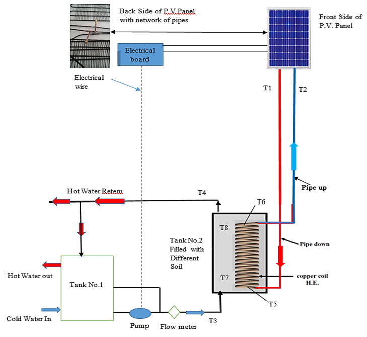
Fig. 1. Schematics of the experimental test rig
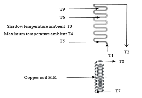
Fig. 2. Location of thermocouple on the Serpentine shape (condenser) behind the P.V. Panel and helical coil
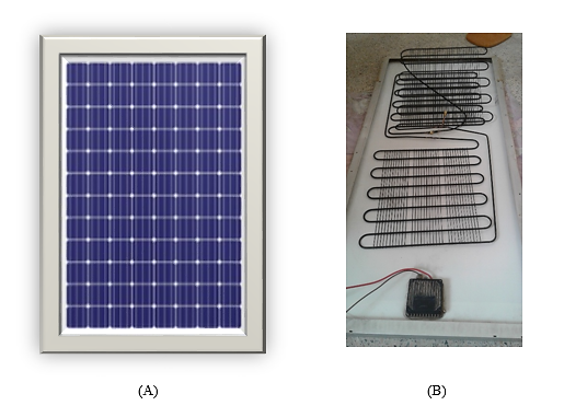
Fig. 3. (A) Front side and (B) back side of P.V. panel
Table 1. Mechanical properties of soil and sand
|
Mechanical Property |
Soil (Typical Clay) |
Sand (Clean, Uncompacted) |
Description & Notes |
|
Moisture Content (w %) |
20% - 50% (can be higher) |
~5% - 15% |
Clay soil absorbs and retains water much more than sand. |
|
Grain Size Distribution (Sieve Analysis) |
More than 50% of particles finer than 0.075 mm (Sieve #200). |
More than 50% of particles between 0.075 mm and 4.75 mm. |
Clay: Fine, smooth particles. Sand: Course, visible particles. |
|
Coefficient of Permeability (k) |
Very Low: 10⁻⁷ to 10⁻¹¹ m/sec |
Medium to High: 10⁻² to 10⁻⁵ m/sec |
Fundamental difference: Sand is porous and permeable, clay is semi-impermeable. |
|
Angle of Internal Friction (φ) |
Low: 0° - 25° (depends on saturation & rate) |
Medium to High: 28° - 40° (depends on density & gradation) |
Shear strength of sand depends on interparticle friction. |
|
Cohesion (c) |
Medium to High: 5 - 50 kN/m² or more |
Zero or negligible (in clean sand) |
Shear strength of clay depends on cohesion (attractive forces between fine particles). |
Table 2. The thermal properties of soil and sand
|
Type |
Thermal conductivity (W/m K) |
Dry density (kg/m3) |
Specific heat (kJ/kg .K) |
Thermal diffusivity (m2/day) |
|
Soil |
0.90-1.90 |
1285 |
0.73 |
0.05–0.12 |
|
Sand |
0.2 - 0.7 |
1400-1800 |
0.7-0.95 |
0.072 |
3 Results and discussion
Figure 4 shows the variation of the outlet-fluid temperature (50% water, 50% oil) with solar irradiance (W/m²). Temperatures are reported in degrees Celsius (°C) throughout this manuscript for consistency with all other figures. A distinct positive correlation is observed: as solar radiation increases, temperature rises for all measured curves. Curve T2 (collector outlet) consistently records the highest temperature, while T1 (collector inlet) records the lowest; this is physically expected because the fluid absorbs solar thermal energy as it passes through the collector, so the outlet temperature (T2) is necessarily higher than the inlet temperature (T1). This confirms the labeling of the inlet/outlet thermocouples is correct and consistent with the direction of heat gain. The spread between curves at a given irradiance level reflects differences in thermal mass and absorption duration at each measurement location, rather than measurement error.
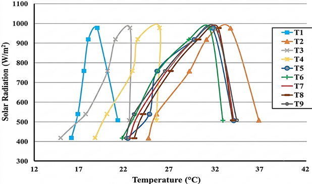
Fig. 4. Variation in Temperature due to Solar Energy: T1: Temp in to collector, T2: Temp out of collector, T3: Shadow temperature ambient, T4: Ambient temperature (maximum), T5: ambient temperature inside the water collector, T6: ambient temperature outside the water collector, T7: Temperature inner collector oil, T8: Temperature outer collector oil, T9: Temperature financing of the collector.
Figure 5 shows the temperature of the water that is flowing out of several high storage materials (HSM) with natural convection. In the charging step, the Composite sand - soil (CSS) gives a less temperature of the solar cell because the liquid (50%water and 50% oil) has significant effects on the performance. The Composite Sand-Soil (CSS) system delivers a higher output water temperature compared to Pure Sand (PSA) or Pure Soil (PSO) assemblies, due to its enhanced thermal storage capacity and improved thermal conductivity, which facilitates greater heat absorption. In clearing step, the (CSS) to get results in comparison with others; the (CSS) gives the heat during (3300 sec), but the (PSA) get heat during (2700 sec) and (PSO) (1980 sec) when reaching a temperature of the water so as an ambient temperature.
The sand-soil composite had a high outlet temperature than (PSA) or (PSO) during charging. This is because of the fact that the composite has most thermal conductivity thus more heat is absorbed. The sand-soil composite seemed to work best during discharging, as the material emitted heat within 55 minutes when compared to pure sand and pure soil, which in comparison, emitted heat in a 45 minutes and 33 minutes, respectively.
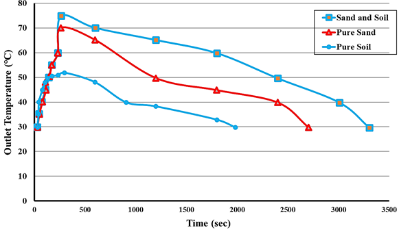
Fig. 5. Temperature of Output water (Natural Convection) against Time with several high storage material (HSM)
Figure 6 presents the influence of water flow rate on the outlet water temperature for sensible heat storage materials including pure sand, pure soil, and the composite sand-soil under conditions of forced convection. Experiment results show that the rate of water flow is inversely proportional to the outlet temperature because of the increased amount of convective heat exchange between the cylindrical coil and the water.
Under forced convection with flow rate of 0.008 kg/s, the durations for heat release are 2700 seconds for the sand-soil composite, 2520 seconds for pure sand, and 1680 seconds for pure soil.
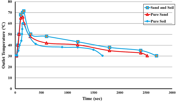
Fig. 6. Effect of High-Storage Materials (HSM) on the Transient Output Water Temperature in Forced Convection (ṁ = 0.008 kg/s)
Figure 7 shows the reading of the thermocouple for the charging and discharging process under forced convection. This is because the charge in the process of charging is high in the case of the composite sand-soil than the other materials. That can be explained by the fact that the composite sand-soil has a higher thermal conduction than the pure sand or pure soil, which leads to a higher heat penetration. Under a water flow rate of 0.016 kg/s, the durations for heat release are: 2580 seconds for the sand-soil composite, 2100 seconds for pure sand, and 1500 seconds for pure soil.
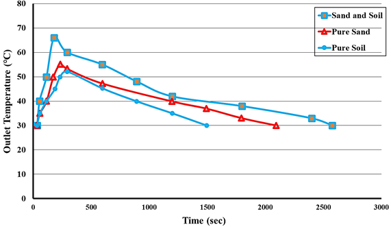
Fig. 7. Effect of high storage materials (HSM) on the transient output water temperature in forced convection (m = 0.016 kg/s)
Figure 8 illustrates the temperature change relative to the pure sand water heat sink under natural and forced convection. The temperature gradient indicates that, under forced convection, the sand temperature rises along tank 1 at a mass flow rate of 0.008 kg/s. The experiment measured the time required for heat dissipation. Under natural convection, the pure sand took 2700 seconds to release its heat. With forced convection of water at a flow rate of 0.008 kg/s, the cooling time decreased to 2520 seconds. Increasing the flow rate to 0.016 kg/s further reduced the cooling time to 2100 seconds.
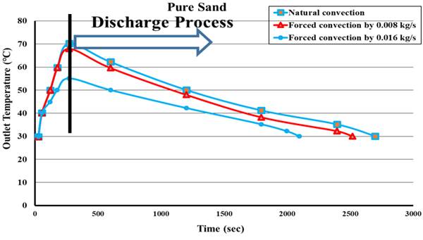
Fig. 8. Effect of convection mode on outer water temperature during discharge process for pure sand (PSA)
Figure 9 shows the amount of useful heat gained by the sensible, composite, and latent thermal materials in the forced convection system at a flow rate of 0.008 kg/sec. The useful heat gain time is inversely proportional to the mass flow rate for the same sensible and composite thermal materials. The heat release time for pure soil is 1980 seconds under natural convection. When forced convection is applied with a water flow rate of 0.008 kg/s, this time decreases to 1680 seconds. Doubling the flow rate to 0.016 kg/s further reduces the heat release time to 1500 seconds.
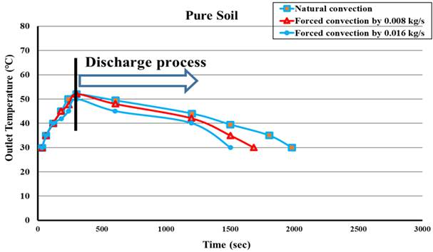
Fig. 9. Effect of convection mode on outer water temperature during discharge process for pure soil (PSO)
Figure 10 illustrates the performance of the composite sand-soil (CSS) consistently provides a greater amount of usable heat compared to pure sand or pure soil during both the charging and discharging phases. The data also highlight the effect of the convection pattern and flow rate on the discharge time:
- In a natural convection system, the CSS composite material releases its stored heat in approximately 3300 seconds.
- When forced convection is applied at a flow rate of 0.008 kg/s, the discharge time of the CSS composite material decreases significantly to 2700 seconds.
- Increasing the flow rate to 0.016 kg/s further shortens the discharge time to approximately 2580 seconds.
In summary, the CSS composite material is the most efficient thermal material tested, and the use of forced convection especially at high flow rates significantly accelerates heat release compared to natural convection.
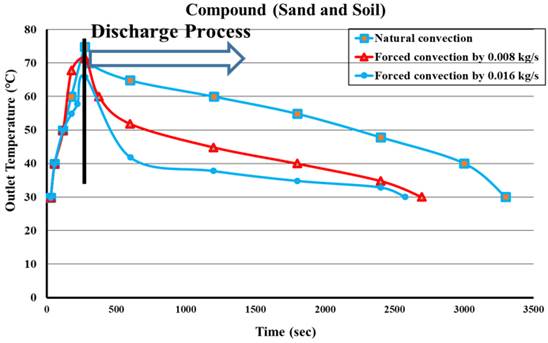
Fig. 10. Effect of convection mode on outer water temperature during discharge process for (CSS)
Figure 11 shows the temporal behavior of thermal storage efficiency for three types of materials (Sand and Soil mixture, Pure Soil, and Pure Sand) with forced water convection at a low constant mass flow rate of 0.008 kg/sec. This figure provides the following scientific insight: General characteristic of thermal charging, all curves are similar in general behavior because they just describe the physical nature of thermal charging for porous materials:
Phase 1 (Extreme efficiency): Initially, (time ≈ 0) All materials have a thermal storage efficiency close to 100%. This is to be expected because the materials start in the state of maximum thermal disequilibrium with respect to the incoming hot water, which maximizes the rate of heat transfer.
Phase 2 (Rapid Decline): A few moments after beginning, efficiency reduces quickly and steeply with every material. This decrease is due to the temperature of the layers close to material surface increases rapidly, which reducing the temperature difference (the driving force for heat transfer) between hot water and material surface.
Phase 3 (Gradual Decline - Approaching Saturation): After about 100-150 seconds, the decline curve stabilizes and slows The materials reached a phase of impending thermal saturation (i.e., maximum heat storage capacity under these conditions). Towards the end of this time period at 500 seconds the efficiency reaches an equilibrium state, indicating that the materials are now mostly saturated, preventing them from effectively storing heat.
This figure provides a clear comparison between the three types of materials, which can be ranked in descending order of efficiency throughout the experiment as follows:
3.1.1 Sand and soil mixture: most efficient
This mixture has the highest thermal storage efficiency for all time during testing. The curve of it is close to the top of the graph. This shows that the mixtures will have superior thermal physical characteristics than that of the pure constituent constituents.
Increased Specific Heat Capacity: Soil can raise the bulk of custodial heat amounting to kilograms of warmth per degree temperature change that could be retained in a combination.
Increased Thermal Conductivity: The different sizes (sand and soil) may compete, which would be beneficial to the contact between the grains, and this is how the thermal conductivity of the bed would increase because the heat may move faster and at the more, deeper location.
Changed porosity: By mixing an optimal pore size distribution, as a result, convective heat transfer through air in the porous layer can be improved.
3.1.2 Pure soil: the second in terms of efficiency
Soil may inherently contain organic matter and fine minerals that provide it a suitable heat capacity. However, its thermal conductivity might be less than the sand due to its more cohesive structure and potentially different (perhaps lower) porosity compared to sand, which could decrease the speed of heat penetration.
3.1.3 Pure sand has the least thermal storage efficiency
Sand does have good thermal conductivity at the level of the particles, but because sand grains are relatively uniform in size, it has a lot of large air gaps between them that can create very high thermal resistance. The air that is cavity locked in these cracks is a bad conductor of heat. Thus, heat transfer occurs very fast through contact points of grains, while penetration of heat in voids and heating water inside is slower, therefore this results low overall performance thermal storage capacity.
In the case of forced convection with flow rate of (0.008 kg/s), heat transfer from the water to the material is more than in natural convection. Specifically, at this low flow rate and with the water flowing fast enough to help heat transfer to superficial layers but not high-pressure enough to penetrate the depth into the material too quickly. That accounts for the initial sharp drop and slower decline thereafter. Therefore, the correct selection of material properties (for instance, the mixture ratio of sand and soil) is vital during a thermal charging process with low water flow rates.
The Sand and Soil mixture is the optimum thermal storage considering such conditions (forced convection of 0.008 kg /s). This composite demonstrates improved thermophysical characteristics, and perhaps this is because of the capability of it to attain a superior level of balance between the heat capacity and the thermal conductivity, and therefore it makes it as one of the few suitable materials to be utilized in thermal energy storage system. The unquestionable power of the mixture shows the synergy among the members of the integral components. The sand-soil composite during the discharge process worked best over an extended duration of time up to 77% and it attained its final value after 580 seconds. The corresponding increase in the mass flow rate to the level of 0.016 kg/s leads to a reduction in the scope of the thermal storage efficiency over time, as seen in Figure 12.
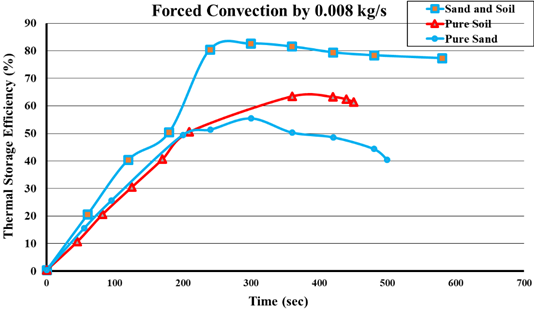
Fig. 11. Thermal-storage (charging) efficiency versus time for the three storage materials (sand-soil mixture, pure soil, pure sand) under forced convection at a mass flow rate of 0.008 kg/s
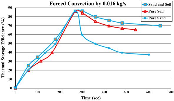
Fig. 12. Forced convection efficiency of huge capacity thermal storage materials at a mass flow rate value of 0.016 kg/sec
4 Conclusions
This experimental study demonstrates that a passive, thermosiphon-driven PV cooling system integrated with a low-cost sand-soil thermal storage medium is a practical solution for hot climates such as Baghdad, Iraq. The following conclusions are directly supported by the experimental results:
- The thermosiphon copper-coil heat exchanger reduced the PV panel temperature by 37.5% under natural convection, confirming its viability as a passive cooling mechanism for solar cells.
- Among the tested media, the composite sand-soil (CSS) storage material combined with the 50% water/50% oil heat-transfer fluid gave the best thermal-storage performance, reaching 77% efficiency within 580 s at a flow rate of 0.008 kg/s and 70% efficiency within 650 s at 0.016 kg/s, compared with only 40% (500 s) and 37.5% (600 s) for pure sand at the same flow rates — a 39.44% improvement. During the discharge phase under forced convection at a flow rate of 0.008 kg/s, the system achieved a thermal storage efficiency of 77% within 580 seconds. With a higher flow rate of 0.016 kg/s, the efficiency reached 70% within 650 seconds. In comparison, using pure sand as the storage medium resulted in significantly lower efficiencies of 40% (within 500 seconds) and 37.5% (within 600 seconds) for the same flow rates, respectively.
- Increasing the mass flow rate consistently shortened the duration of constant outlet-water temperature during discharge, for all three storage materials.
- The sand-soil composite sustained a lower outlet-water temperature for longer than pure sand or pure soil under every convection condition tested (3300 s under natural convection vs. 2700 s for pure sand and 1980 s for pure soil), confirming its superior sensible heat-storage capacity. For CSS (50% soil/50% sand with 50% water/50% oil) under natural convection, the outlet water temperature was maintained at a lower temperature for a longer period (3300 seconds), indicating sustained heat release. During operation, the charging phase increases heat absorption, while the discharge phase reduces the temperature. In contrast, using pure soil under forced convection at a high flow rate (0.016 kg/s) resulted in a much shorter outlet water temperature reduction period (1500 seconds).
- Natural convection produced the longest heat-emission duration for the sand-soil mixture, followed by forced convection at 0.008 kg/s, with forced convection at 0.016 kg/s giving the shortest emission time — confirming an inverse relationship between flow rate and thermal-storage duration.
Acknowledgements
The authors acknowledge their thanks to the faculty of the College of Mechanical Engineering, University of technology- Iraq.
References
- Neuberger, P., Adamovský, R., & Šeďová, M. (2014). Temperatures and heat flows in a soil enclosing a slinky horizontal heat exchanger. Energies, 7(2), 972–987. https://doi.org/10.3390/en7020972
- Khurshid, S., Karthik, S., & Hassan, H. (2019). The design of shell and tube heat exchangers – A review. International Journal of Mechanical and Production Engineering Research and Development, 9(1), 87–102.
- Alqatamin, A., & Jinzhan, S. (2025). Experimental investigation of the photovoltaic thermal integrated with ground heat exchanger using volcanic tuff stones. Applied Thermal Engineering, 263, Article 125357. https://doi.org/10.1016/j.applthermaleng.2024.125357
- Somwanshi, A., & Sarkar, N. (2020). Design and analysis of a hybrid air and water cooler. Engineering Science and Technology, an International Journal, 23(1), 101–113. https://doi.org/10.1016/j.jestch.2019.04.010
- Yoon, J. I., Son, C. H., Choi, K. H., Kim, Y. B., Sung, Y. H., & Roh, S. J. (2018). Performance characteristic of hybrid cooling system based on cooling pad and evaporator. Proceedings of the 8th TSME International Conference on Mechanical Engineering.
- Tu, S., Yang, X., Zhou, X., Luo, M., & Zhang, X. (2019). Experimenting and modeling thermal performance of ground heat exchanger under freezing soil conditions. Sustainability, 11(20), Article 5707. https://doi.org/10.3390/su11205707
- Abdullah, Z. B. (2021). Combining heat-pipes heat-exchanger and solar energy for comfort cooling [Doctoral dissertation, Universiti Teknologi Malaysia].
- Zarei, A., Seddighi, S., Elahi, S., & Örlü, R. (2022). Experimental investigation of the heat transfer from the helical coil heat exchanger using bubble injection for cold thermal energy storage system. Applied Thermal Engineering, 200, Article 117627.
- Ali, A. A., Alfarge, D., Rashid, F. L., Ugla, A. A., Kareem, A. K., & Mohammed, H. I. (2025). Improving photovoltaic panels by utilizing ground-coupled heat exchangers: Insights and technological advances. Geothermics, 130, Article 103155. https://doi.org/10.1016/j.geothermics.2024.103155
- Gil, S., Gradon, B., & Bialik, W. (2017). Experimental studies on the hybrid system of heat and cold production from solar energy. Thermal Science, 21(6A), 2827–2835. https://doi.org/10.2298/TSCI160120155G
- Bashir, M. A., & Ali, H. M. (2025). Numerical investigation of passive cooling of the PV module using extended fin heat sinks: A parametric analysis. Process Safety and Environmental Protection, 195, 1–14. https://doi.org/10.1016/j.psep.2024.12.001
- Ülker, H. B., Akagündüz, M. U., Sancar, I., & Nergiz, C. (2026). Cooling of PV panels with earth–air heat exchanger and novelly designed plenums: An experimental study. Arabian Journal for Science and Engineering. Advance online publication. https://doi.org/10.1007/s13369-024-09855-y
- Noori, S. W., Shkarah, A. J., Lafta, D. A., Lafta, A. M., & Mansour, M. M. (2025). Enhancing the performance of photovoltaic panels by controlling external climatic parameters: An experimental study. European Journal of Sustainable Development Research, 10(2), Article em0255.
- Pérez Grajales, S. G., Hernández Ortíz, T., Martinez-Oropeza, R., & Torres, T. (2024). Prediction of heat transfer in a hybrid solar–thermal–photovoltaic heat exchanger using computational fluid dynamics. Processes, 12(10), Article 2215. https://doi.org/10.3390/pr12102215
- Al-Kayiem, H. H., & Reda, M. N. (2021). Analysis of solar photovoltaic panel integrated with ground heat exchanger for thermal management. International Journal of Energy Production and Management, 6(1), 1–15. https://doi.org/10.2495/EQ-V6-N1-1-15
- Farag, A., Emam, M., Ookawara, S., & Nada, S. (2025). The effectiveness of ground source heat exchangers for sustainable cooling in commercial buildings: A comprehensive evaluation. Applied Thermal Engineering, 262, Article 125150. https://doi.org/10.1016/j.applthermaleng.2024.125150
- Atwany, H., Hamdan, M., Attom, M., Abu-Nabah, B. A., & Alami, A. H. (2019). Performance of earth-water heat exchanger for cooling applications. The International Journal of E-Learning and Educational Technologies in the Digital Media, 5(1), 17–21.
- Zarazvand, B., Frankovska, J., & Kopecky, M. (2025). Numerical study of soil saturation effects on the thermal performance of a horizontal geothermal heat exchanger. Civil and Environmental Engineering, 21(1), 1–16. https://doi.org/10.2478/cee-2025-0001
- Agrawal, K. K., Misra, R., & Agrawal, G. D. (2020). Improving the thermal performance of ground air heat exchanger system using sand-bentonite (in dry and wet condition) as backfilling material. Renewable Energy, 146, 2008–2023. https://doi.org/10.1016/j.renene.2019.08.053
- Chaich, Z., Belatrache, D., Labiod, L., & Bourouis, M. (2026). Enhancing the efficiency of solar photovoltaic systems via smart cooling in arid environments. Applied Thermal Engineering, 292(Part 1), Article 130257. https://doi.org/10.1016/j.applthermaleng.2026.130257
- Necib, H., Kadi, H., Belatrache, D., & Hammou, Y. B. (2025). Experimental evaluation of water cooling effects on photovoltaic module performance in a hot climate. International Journal of Energy and Water Resources, 9(3), 1467–1483. https://doi.org/10.1007/s42108-025-00346-y
Conflict of Interest Statement
The authors declare that there is no conflict of interest regarding the publication of this paper.
Author Contributions
Data Availability Statement
All relevant data are included within the article.
Supplementary Materials
There are no supplementary materials to include.