Original Scientific Paper, Volume 23, Number 2, Year 2025, No 1266, pp 208-219
Received: Aug 22, 2024 Accepted: May 20, 2024 Published: Jun 16, 2025
DOI: 10.5937/jaes0-52938
EXPERIMENTAL STUDY OF SHEAR STRESSES OF SOLID AND HOLLOW CONCRETE BEAMS MADE WITH WASTE TIRE RUBBER
Abstract
Numerous studies have suggested using alternative materials in concrete; waste tire rubber is one such item which has drawn a lot of interest. Furthermore, tire landfilling—one of the biggest ecological issues facing the planet in the near future can be avoided by reusing and recycling waste tire rubber. The rubber crumb waste is added to concrete mixtures at those percentage values of 0%, and 15% as substitute by coarse aggregate weight. This research investigates the Shear and Flexural Behaviour and Action of Reinforced Solid Recycled Rubber Concrete Beams (SRRCB) and Reinforced Hollow Recycled Rubber Concrete Beams (HRRCB) composed of Tire Rubber Crumb and Granular Waste under a two-point load. The flexural behavior of HRRCB and SRRCB was assessed and calculated in the presented work using a four-point bending test on six reinforced concrete solid and hollow beams. Beams prepared with 230 mm height, 1000 mm length, and 120 mm are described in this study. Rubber aggregate influence as partial substitute for the fine aggregate in the concrete was investigated by looking at the beam response. To assess test units’ failure pattern, the experimental beams have been compared to normal-weight concrete. Comparing a beam with a 15% rubber aggregate replacement ratio to one with conventional aggregate concrete, the load behavior was identical. According to the findings, hollow opening had impact on HRRCB's Ultimate Load Level Capacity and Deflection. In order to lower the overall cost and weight of HLC beams, greater customization of the beam's construction and design features is possible. Due to the fact that their response is identical to that of beams constructed with conventional concrete, ultimate load of beams that are produced with 15% recycled rubber aggregate concrete might be complimented and utilized. Findings have played a role in the understanding of the mechanical performance and failure mechanisms of these beams, offering valuable information about potential applications of the recycled Tire Rubber aggregates in structural engineering. Based on this premise, the study was undertaken to investigate shear behaviour of the hollow and solid concrete beams incorporating recycled Tire Rubber aggregates, aligning with ongoing efforts of sustainability in the construction.
Highlights
- Investigates Shear & Flexural Behavior: Examines both shear and flexural performance of Solid (SRRCB) and Hollow (HRRCB) Reinforced Recycled Rubber Concrete Beams using waste tire rubber.
- Experimental Methodology: Employs four-point bending tests on six reinforced beams (3 solid, 3 hollow) to assess flexural behavior under two-point loading.
- Key Finding on Replacement Ratio: Reveals that beams with 15% rubber aggregate replacement exhibit identical load behavior to conventional aggregate concrete beams.
- Sustainable Application Focus: Demonstrates the structural engineering potential of recycled tire rubber aggregates, contributing to construction sustainability.
Keywords
Content
1 Introduction
In various nations worldwide, the handling of waste tires was a major cause of concern [1]. In concrete mixes, Alharishawi et al. substituted up to 20% of the fine aggregates with glass and ground plastics and up to 20% of the coarse aggregates with crushed concrete. The investigation's primary conclusions showed that the 3 waste aggregate material categories may be effectively repurposed as partial substitutions for the sand or the coarse aggregates in the mixes of concrete [2-8]. Accumulation of this waste is discovered to be extremely risky, not just because it may have adverse effects on the environment, but also since it poses a fire hazard and serves as a breeding ground for rodents. [9–12]. Rubber concrete samples performed better compared to ordinary concrete in the Goulias et al. test of flexibility execution. The results showed severe deformity without complete concrete deterioration [13]. The integration of rubber aggregates that have been derived from waste tires into concrete, according to Sgbobba et al., is a workable way for certain engineering manufacturers to reduce weight [14]. Samples prepared to 25% and 20% rubber in the concrete had offered good performance at water-cement ratio of 0.4 and 0.45, respectively, according to data obtained in shrinkage characteristics’ examination of the rubberized concrete pavements [15].
With a greater quantity of rubber chips, Ali and Goulias discovered that the material modulus and rigidity of rubber decreased, indicating a less brittle material [1]. In situations when vibration damping is necessary, Avcular and Topcu suggested using rubber-treated concrete [16]. Fattuhi and Clark also expressed comparable opinions [17]. The results show that plain concrete's high density and compressive strength are preferred for the good level of impact resistance. Zhu had also announced that steel filament consolidation enhanced impact resistance [18]. According to Hernandez-Olivaries etal., there has not been any considerable difference in the mechanical characteristics of the concrete when tire rubber volume divisions as high as 5% were used in a concrete framework [19]. Better quality concrete can be produced from tire rubber waste, as demonstrated by G. S. Kumaran etal., by incorporating industrial waste materials and admixtures as cement partial substitution [20]. According to Portchejian G. and Nithiya P., the amount of crumb rubber substitution decreases compressive quality. In the case when rubber replaces up to 10% of fine aggregate, split tensile strength is decreased by at most 25%. When rubber scraps increase by up to 10%, concrete's flexural quality increases [21]. According to O Youssf et al., structural planners considering using CRC (crumb rubber concrete) as one of the viable alternatives to the conventional concrete in the seismic zones may find assistance from his model [22]. The best replacement amount, according to R. Dr. C. Natarajan and Bharathi Murugan, is 15% rubber substance. This reduces concrete’s compressive quality, yet it still has some appealing qualities, such as high flexural quality, low density, and high durability [23]. According to research by Hanbing Liu et al., adding rubber fragments to concrete significantly reduced its mechanical qualities while increasing its durability. Senthil [24], the primary concerns of Vadivel et al. are Tyre Rubber Aggregate Concrete (TRAC) strength, deflection, ductility, and durability. Pure reinforced concrete has superior ductility than conventional concrete, according to tests on beams [25–28]. Foam concrete was improved by adding waste tire steel (WTS) and rubber particles (RP), with Taguchi and ANN methods helping to optimize the mix for sustainable construction [29]. In reinforced concrete beams (RCBs), 2.5% waste tire rubber (WTR) increased deformation capacity (from 3.89 cm to 7.69 cm) and boosted seismic performance under near-fault earthquakes, based on 3D FEM results [30]. Although higher amounts of rubber reduced the beams’ mechanical strength, using 5% rubber achieved a good balance between environmental benefits and structural safety according to code requirements [31]. Adding between 0% and 15% waste rubber led to energy absorption and load capacity losses of up to 62.44%, showing a clear trade-off between sustainability and performance [32].
As the material is still in its early stages, the exploration actually focuses on waste tires. There’s hardly any literature available in the structural applications field. To enhance their fundamental structural applications in development of construction, it is imperative to identify the key characteristics of tire rubber aggregate concrete beams under such conditions. With such a background, the present study has been planned. This manuscript details well-structured experimental research that involved 12 reinforced concrete beams with a variety of steel ratio values and a variety of the aggregate kinds, which includes recycled as well as virgin tire rubber aggregates. The beams have been subjected to 2-point loading, with ultimate moments, cracking moments, and failure patterns recorded for comparison to the virgin tire aggregates. The potential results include enhanced section ductility due to the influence of load eccentricity, strength, deflections, load curvature, and moment interaction diagram. The main objective of the present work is to examine the impact of a variety of parameters on the ultimate shear strength of twelve test RCB beams. Furthermore, the impact of HRRCB on the flexural behaviour under mid-span deflection, load-carry level capacity, and shear behaviour of HRRCB and Concrete Beam under combined flexural strength and shear strength is represented by flexural response of reinforced Hollow Concrete beams (HRRCB) that are produced with tire rubber crumb and granular waste and the Solid Concrete Beams (SRRCB) made with tire rubber crumb and granular waste. Furthermore, this work's investigative outcomes were contrasted with those of SCB and HCB [33].
2 Materials and methods
In this study, RCB have been created using Tire Rubber Crumb and Granular Waste as fine aggregate, Box Plastic, Portland Cement, and Steel Reinforcing Bars as the raw materials.
2.1. Materials and testing procedures
This paper had made use of Portland cement. Portland cement has a compressive strength of 33 and 41N/mm2 in 3 and 7 days, respectively. As Fine Aggregate (NS), Natural Sand with a Maximum Size of 4.75mm, has been utilized. The gravel employed in the experiment as a coarse aggregate (NG) should be clean and completely crushed, with a 10mm maximum size. For the past 25 years, waste tires have been utilized in experimental research for the partial substitution of the aggregate in both conventional concrete and self-compacting concrete. Rubber aggregate from the tire grinding of worn-out tires was primarily used to replace tire and tire grinding. Tire waste is used to make rubber particles in concrete. Either at ambient temperature or at cryogenic temperatures, a mechanical process takes place. Based on the size, form, and substituted material of the rubber, waste tire rubber may be divided into four categories, as shown in Figure 1 [34]. Rubber crumbs and granular materials have been utilized in this study's experimental activity. In the experimental work, tap water was used.
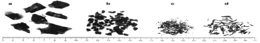
Fig. 1. Categorization of waste rubber aggregates: (a) chipped, (b) crumb, (c) granular, and (d) fiber [34]
2.2. Steel reinforcement
All of the beams in this project are longitudinally reinforced through steel bars with diameters of 12 mm, 16 mm, 4 bars, and 6mm, as shown in Figure 2. Table 1 lists steel reinforcement bar characteristics, and every inspection of steel bars compliance with the ASTM standards.
Table1. Mechanical Characteristics of Steel Bars
|
Steel Bar Diameter |
Bar Type |
Yield Strength (fy) |
Ultimate Strength (fu) |
Max. Elongation (%) |
|
16mm |
Ribbed |
523MPa |
628MPa |
18 |
|
12mm |
Ribbed |
627MPa |
741MPa |
20 |
|
6mm |
Round |
452MPa |
481MPa |
28 |
2.3. Box plastic
For the HCB [4], box plastic of 50 * 75 * 1000 mm was used, as shown in (Fig 2).
 Fig. 2. Steel Reinforcement Bars and Plastic Box [4]
2.4. Mixtures
Table 2. indicates concrete mix by weight.
Table 2. Mixtures
|
Mix No. |
Portland Cement (C), (kg/m3) |
Coarse Aggregate (kg/m3) |
Fine sand (F.S) (kg/m3) |
Rubber Crumb & granular (kg/m3) |
w/c |
|
|
Coarse Aggregate (kg/m3) Replacement of rubber crumb & granular (%) by weight |
Rrubber & granular (kg/m3) |
|||||
|
Group 1 |
340 |
850 |
600 |
0% |
0 |
0.45 |
|
Group 2 |
340 |
850 |
500 |
15% |
100 |
0.45 |
2.5. Specimens
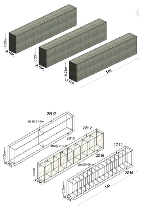
Specimens used are reinforced HRRCB with a width * full depth of 230 * 120 mm (cross section). The dimensions of beams and the calculated steel reinforcement ratios adhered to specification limits, ensuring accuracy in the results. A 75 * 50 mm hollow section is prepared in the center of the beam section. Additionally created for comparison and examination have been specimens lacking a hollow section known as SRRCB. The concrete cover, or the distance between the cross-section’s border and stirrup, measures 20 mm. The specifics of the RCB cross-section have been depicted in (Fig 3). For normal-weight concrete (Group 1), the average (fcu) was (35 MPa) [33], while for concrete prepared with tire rubber crumb and granular waste (Group 2), it was (26 MPa). Steel reinforcement Bars with (6mm) diameter vertical stirrups steel bar was made at distances of 450mm, 130mm, and 60mm as it has been depicted in (Fig 4).
|
a. HCB b. SCB |
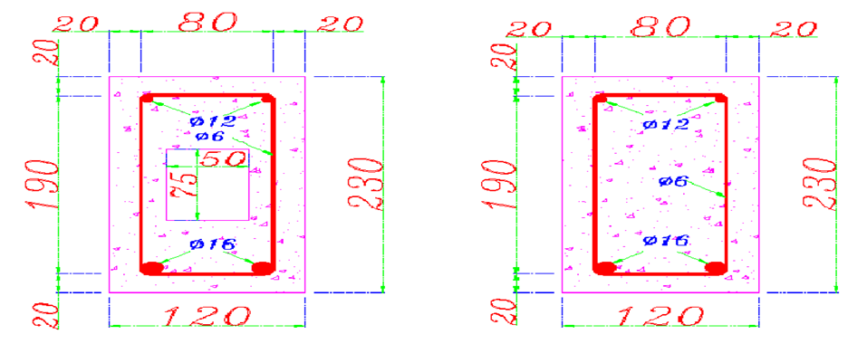
Fig. 3. CB Cross Section: a) SRRCB & b) HRRCB
 |
 |
| a. SCB | b. HCB |
Fig. 4. CB Cross Section: a) SRRCB & b) HRRCB; Note: All of the Dimensions are in millimeters [4]
2.6. Specimen preparation
Each one of the specimens has been produced in the lab. All of the HRRCBs and SRRCBs were cast using mixed concrete. Beams were taken out of the tank that contained the curing water after a day, in particular after 28 days. Cube concrete samples (15cm * 15cm).
2.7. Test program
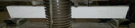
SRRCB and HRRCB structural responses, one dial gauge (ELE type). As shown in (Fig. 6), it was positioned below the RCB at mid-point to confirm downward deflection.
|
Fig. 5. HRRCB and SRRCB out of the Water [33] |
a) Side View
b) Testing Machine
Fig. 6. Test Instrumentation: a) Side View and b) Testing Machine [33] |


3 Results and discussion
Six RRCB specimens have been looked at in the present study. The RCB has identical measurements for the thickness, width, and length. As the web reinforcement, a number of steel stirrup bars with 6mm diameter values were produced at distances of 450mm, 130mm, and 60mm. Three SRRCB without hollow have been present in six RCB types (S13 RRCB, S45 RRCB, S6 RRCB). The 3 additional HRRCBs (O13 RRCB, O45 RRCB, and O6 RRCB) poured a cavity of 50 by 75mm along a 1000mm al beam.
3.1 Cracking of solid and hollow RC beams
Table 3 displays cracking test results and load-carry level capacity. SRRCB and HRRCB samples have been subjected to the Load Level (kN) (i.e., Experimental) carry capacity; at approximately (17–30%) of the Load Level (kN) (i.e., Experimental) carry capacity for the RCB, the first cracks had emerged. The first crack load (Pcr) for three SRRCB variants (S 45 RRCB, S 13 RRCB, and S 6 RRCB) without a hollow are (14, 15.5, & 16.5kN). The other three HRRCB are (18, 16, and 20) kN, respectively (O13 RRCB, O45 RRCB, and O6 RRCB). Three SRRCB (S13 RRCB, S45 RRCB, S6 RRCB) had values of Ultimate Load Level (Pu) of (82, 67, & 97) kN, while three HRRCB (O 13 RRCB, O 45 RRCB, O 6 RRCB) had values of (63, 52, & 75kN). Three SRRCB (S 13 RRCB, S 45 RRCB, S 6 RRCB) and three HRRCB (O13 RRCB, O45 RRCB, O6 RRCB) RCB models have shown shear cracks occurring after steel reinforcement yields and final RCB crushing in zone of compression (Fig. 7 - 8) and Table 4. There is a relationship between stirrup spacing and crack initiation and pattern, The lower the stirrup spacing means more reinforcing steel, and thus fewer cracks as shown (Fig. 9-10). The larger the cross-sectional area or volume for Pattern (HRRCB and SRRCB), the greater the load capacities and Pattern cracks for solid vs. hollow beams (Fig. 9-10) and Table 4. In the case when put to comparison with six normal weight NCB, all of such RRCB test results were less than around 16% [33]. The study highlights the reduced tolerance of hollow beams to forces compared to solid beams as a result of hollow sections running along the concrete beam.
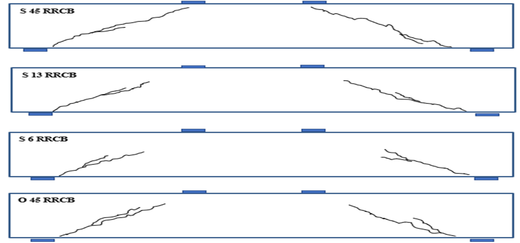

Fig. 7. Beams Failure in Terms of Crack Pattern (HRRCB & SRRCB)

Fig. 8. Beams Failure in Terms of Crack Pattern (HCB and SCB) [33]
Table 3. First Crack and The Load-Carry Level Capacity (HRRCB & SRRCB)
|
Group Name |
Designation of Beams |
fcu (MPa) |
First Crack Load Level (Pcr) (kN) |
Ultimate Load Level (Pu) (kN) |
(%) |
|
SRRCB |
S 45 RRCB |
25.5 |
14.0 |
67 |
20.89 |
|
S 13 RRCB |
26.0 |
15.5 |
82 |
18.90 |
|
|
S 6 RRCB |
25.0 |
16.5 |
97 |
17.01 |
|
|
HRRCB |
O 45 RRCB |
26.0 |
16 |
52 |
30.76 |
|
O 13 RRCB |
25.0 |
18 |
63 |
28.5 |
|
|
O 6 RRCB |
25.5 |
20 |
75 |
26.67 |
Table 4. Deflection (*10-2 mm) - The Load Carry Level Capacity (HRRCB and SRRCB)
|
Load (kN) |
Deflection Solid 45 |
Deflection 45 Hollow |
Load (kN) |
Deflection Solid 13 |
Deflection 13 Hollow |
Load (kN) |
Deflection Solid 6 |
Deflection 6 Hollow |
||
|
0 |
0 |
0 |
0 |
0 |
0 |
0 |
0 |
0 |
||
|
5 |
3 |
5 |
5 |
3 |
19 |
5 |
1 |
1 |
||
|
10 |
6 |
8 |
10 |
4 |
23 |
10 |
3 |
3 |
||
|
14 |
9 |
13 |
15.5 |
10 |
26 |
16.5 |
14 |
8 |
||
|
16 |
14 |
20 |
18 |
12 |
35 |
20 |
12 |
31 |
||
|
20 |
20 |
26 |
25 |
26 |
40 |
25 |
19 |
27 |
||
|
25 |
32 |
37 |
30 |
32 |
57 |
30 |
26 |
44 |
||
|
30 |
42 |
48 |
35 |
40 |
70 |
35 |
33 |
60 |
||
|
35 |
60 |
80 |
40 |
46 |
105 |
40 |
37 |
88 |
||
|
40 |
85 |
105 |
45 |
50 |
120 |
45 |
49 |
110 |
||
|
45 |
110 |
136 |
50 |
65 |
150 |
50 |
52 |
134 |
||
|
50 |
135 |
167 |
55 |
80 |
185 |
55 |
70 |
172 |
||
|
52 |
150 |
193 |
63 |
100 |
210 |
60 |
83 |
212 |
||
|
60 |
180 |
65 |
120 |
65 |
102 |
253 |
||||
|
67 |
215 |
70 |
163 |
70 |
121 |
304 |
||||
|
75 |
192 |
75 |
163 |
341 |
||||||
|
80 |
200 |
80 |
192 |
|||||||
|
82 |
240 |
85 |
202 |
|||||||
|
90 |
211 |
|||||||||
|
95 |
221 |
|||||||||
|
97 |
273 |
Figures (9-10) display and summarize the relationship between the first crack load and ultimate load for each beam. It clarifies the hollow geometry delays initial cracking. And that improving the ductility of concrete.
|
Fig. 9. First crack load for HRRCB and SRRCB - Distance Stirrup Steel Bar |
Fig. 10. Ultimate load for HRRCB and SRRCB - Distance Stirrup Steel Bar |

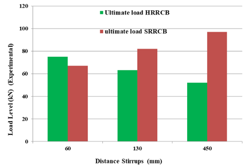
Figure 11 shows the ductility index for each beam designation and shows the deflection increase with an increase in the hollow concrete beams made with waste tire rubber more than solid. Also, the Figure shows detailed deflection measurements and deflection increase vs. stirrup spacing increase. A single table summarizing all beam types, their stirrup spacing, first crack load, ultimate load, mid-span deflection, and failure mode would improve readability and comparison. As minted in the table 4 summarizing all beam types, their stirrup spacing, first crack load, ultimate load, and mid-span deflection.
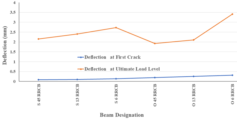
Fig. 11. Ductility index (ultimate deflection / deflection at first crack)
3.2 Ultimate loads level
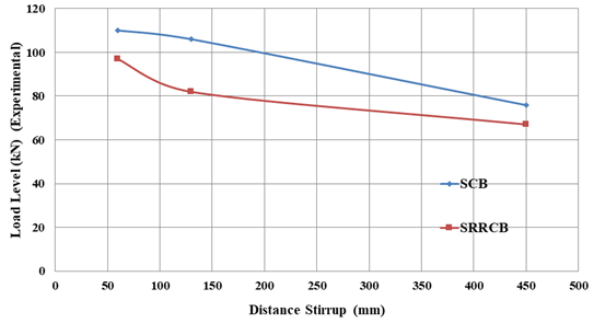
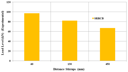
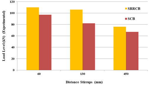
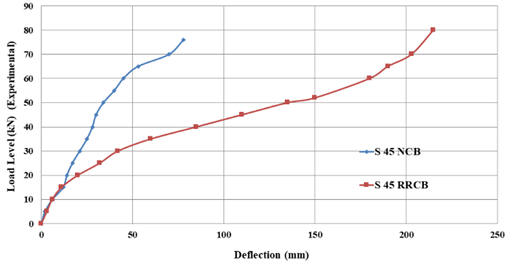
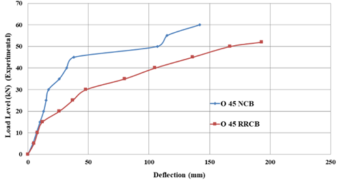
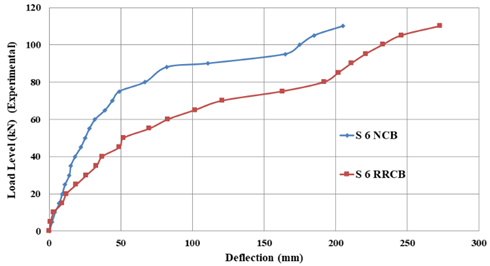
Test results of the ultimate load levels to all of the RCB as specified in Table4 indicate that Load Levels for HRRCB (O13 RRCB, O45 RRCB, O6 RRCB), have been weaker compared to the ultimate loads level for SRRCB (S 13 RRCB, S 45 RRCB, S 6 RRCB) respectively, indicated in (Fig. 12). As demonstrated by comparison of NCB with the RRCB in Figs. (13–14) [33]. As shown in Figures 15–16, distance vertical stirrup bar reinforcement (6mm in diameter) lowers load-carry level capacity for all of the beams (HRRCB as well as SRRCB) rise. As can be seen from Fig. (17–18) [33], NCB and RRCB are compared. Load-carry level capacity of the solid beams (S 13 RRCB, S 45 RRCB, S 6 RRCB) increases by around 20% less than load-carry level capacity of the hollow beams (O13 RRCB, O45 RRCB, O6 RRCB), as shown in (Fig12).

Fig. 12. Load Level (kN) (Experimental) Carry Capacity-Distance Stirrups Steel Bar (60mm, 130mm, & 450mm) Relationships of SRRCB with HRRCB
|
Fig. 13. Load Level (kN) (Experimental) Carry Capacity |
Fig. 14. Load Level (kN) (Experimental) Carry Capacity |
|
Fig. 15. Load Level (kN) (Experimental) Carry Capacity |
Fig. 16. Load Level (kN) (Experimental) Carry Capacity |
|
Fig. 17. Load Level (kN) (Experimental) Carry Capacity |
Fig. 18. Load Level (kN) (Experimental) Carry Capacity |


3.3 Load level–deflection behaviour and ductility of the hollow of solid RC beams
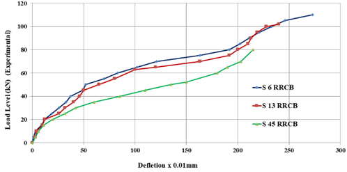
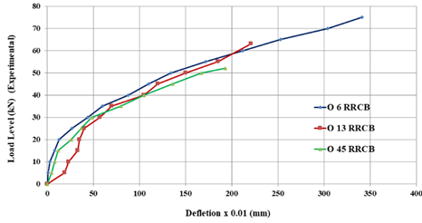
Table 5 displays results of mid-span deflection for the HRRCB and SRRCB. According to the test results, Distance Stirrup steel bar (6 mm diameter) for SRRCB has a maximal mid-span deflection at the ultimate load-carry level capacity of 60 mm, whereas the HRRCB's minimum mid-span deflection is 450 mm. load carrying level capacity-mid-span deflection correlations for beams (HRRCB & SRRCB) were exhibited in (Figs. 19 & 20). The comparison of the RRCB with the normal weight NCB [33] is shown in Figures 21–26.
Table 5. Mid Span Deflection at First Crack and Load Level Carry Capacity
|
Group Name |
Beam Designation |
Mid-Span Deflection at First Crack |
Mid-Span Deflection at Ultimate Load Level |
|
SRRCB |
S 45 RRCB |
0.09mm |
2.15mm |
|
S 13 RRCB |
0.10mm |
2.40mm |
|
|
S 6 RRCB |
0.14mm |
2.73mm |
|
|
HRRCB |
O 45 RRCB |
0.20mm |
1.93mm |
|
O 13 RRCB |
0.26mm |
2.10mm |
|
|
O 6 RRCB |
0.31mm |
3.41mm |
|
Fig. 19. Load Level - Deflection Relationships for SRRCB (S6, S 13, S 45) |
Fig. 20. Load Level - Deflection Relationships for HRRCB (O 6, O13, O 45) |
|
Fig. 21. Load Level |
Fig. 22 Load Level |
|
Fig. 23. Load Level Carry Capacity |
Fig. 24. Load Level Carry Capacity |
|
Fig. 25. Load Level Carry Capacity |
Fig. 26. Load Level Carry Capacity |


4 Conclusions
The findings of experimental research that had been displayed on HRRCB were presented in this work. Six RRCBs in all have been prepared and evaluated using a four-point system. With an ultimate load-carry level beam capacity of 52, 63, or 75kN and a corresponding deflection of 0.19, 0.21, or 0.34 mm, HRRCB describes the specifics of the cracking Load Level beam. The findings further confirmed that the HRRCB's ultimate load level as well as deflection, have not been highly impacted by the hollow opening. In cases where the Distance Stirrup steel bar is at its minimum, SRRCB and HRRCB maximal mid-span deflection at the ultimate load-carry level capacity takes place. For every SRRCB and HRRCB, the ultimate load-carry level capacity is decreased by the Distance Stirrup steel bar (6 mm diameter). Loss of shear area in RRCB compared with NCB gives more ductility for RRCB than NCB. Additionally, the utilization of recycled tire rubber as aggregate in concrete production is emphasized as a promising approach to address the pressing issue of tire waste. However, further research is essential to overcome current limitations, particularly focusing on structural elements such as columns and slabs.
Acknowledgements
The authors would like to thank the College of Engineering at Mustansiriyah University (www.uomustansiriyah.edu.iq), Baghdad, Iraq, for their support and assistance in preparing this study.
References
- Khaloo, A. R.; Dehestani, M.; Rahmatabadi, R. 2008. Mechanical properties of concrete containing a high volume of tire–rubber particles, Waste Management 28: 2472–2482. http://dx.doi.org/10.1016/j.wasman.2008.01.015
- S.S.C. Alharishawi, H. Abd, S.Abass, "Employment of Recycled Wood Waste in Lightweight Concrete Production", Archives of Civil Engineering, 2020, vol. 66, no. 4, pp. 675-688, https://doi.org/10.24425/ace.2020.135244
- Alharishawi, S. S. C., Rajaa, N., & Jabur, A. R. (2023). Laboratory tests of solid and hollow concrete beams made with glass waste. Archives of Civil Engineering, 69(4). https://doi.org/10.24425/ace.2023.147644
- S.S.C. Alharishawi, N. Rajaa, , L. Shihab, "Shear Stresses of Hollow Lightweight Concrete Beams made with Wood Waste". Archives of Civil Engineering, 2021, vol. 67, no. 1, pp. 657-672. https://doi.org/10.24425/ace.2021.136495
- S. Alharishawi, H. Aljumaily, N. Rajaa, "Subject Review: A Comparison of Using Recycled Rubber as Aggregate in Concrete". International Journal of Advances in Scientific Research and Engineering, IJASRE. 2021, vol. 7, no. 2, pp. 65-70. https://doi.org/10.31695/IJASRE.2021.33974
- S. Alharishawi, N. Rajaa, H. Aljumaily, "subject Review: A Comparison of Lightweight Concrete madewith Sawdust". International Journal of Engineering Research andAdvanced Technology, IJERAT, 2021, vol. 7, no. 2, pp. 1-5. https://doi.org/10.31695/IJERAT.2021.3691
- S.S.C. Alharishawi, N. Rajaa, A. Jabur, "Experimental Investigation of using Recycled Glass Waste as Fine Aggregate Replacement in Concrete". Archives of Civil Engineering, 2021, vol. 67, no. 4, pp. 27-38. https://doi.org/10.24425/ace.2021.138484
- Faris, H. A., Alharishawi, S. S. C., & Rajaa, N. (2024, October). Shear Behavior of Solid and Hollow Cylindrical Concrete Beams Made with Recycled Brick. In Annales de Chimie Science des Matériaux (Vol. 48, No. 5). http://dx.doi.org/10.18280/acsm.480503
- Siddique, R.; Naik, T. R. 2004. Properties of concrete containing scrap tire rubber – an overview, Waste Management 24(6): 563–569. http://dx.doi.org/10.1016/j.wasman.2004.01.006
- Ghaly, A. M.; Cahill, J. D. 2005. Correlation of strength, rubber content and water: cement ration in rubberized concrete, Canadian Journal of Civil Engineering 32: 1–7. http://dx.doi.org/10.1139/l05-063
- Hernandez–Olivares, F.; Barluenga, G.; Bollati, M.; Witoszek, B. 2002. Static and dynamic behavior of recycled tire rubber– filled concrete, Cement Concrete Research 32: 1587–1596. http://dx.doi.org/10.1016/S0008-8846(02)00833-5
- Li, G.; Garrick, G.; Eggers, J.; Abadie, C.; Stubblefield, M. A.; Pang, S. 2004. Waste tire fiber modified concrete, Journal of Composite 35: 305–312. http://dx.doi.org/10.1016/j.compositesb.2004.01.002
- Goulias, D. G. and Ali, A. H., 1997, “Non-Destructive Evaluation of Rubber Modified Concrete,” in Proceedings, Special Conference ASCE, New York, NY, pp. 111–120.
- Sgobba, S.; Marano, G. C.; Borsa, M.; Molfetta, M. 2010. Use of rubber particles from recycled tires as concrete aggregate for engineering applications, in Second International Conference on Sustainable Construction Materials and Technologies, 28–30 June 2010, Universita politecnica delle Marche, Ancona, Italy.
- Mohammadi, I.; Khabbaz, H. 2015. Shrinkage performance of Crumb Rubber Concrete (CRC) prepared by water–soaking treatment method for rigid pavements, Cements and Concrete Composite 62: 106–116.
- Topcu, I.B. and Avcular, N. “Collision behaviors of rubberized concrete”, Cement and Concrete Research 27 (12), pp.1893-1898, 1997.
- Fattuhi, N.I. and Clark, N.A. “Cement-based materials containing tire rubber”, Journal of Construction and Building Materials, Vol.10, No.4, pp.229–236, 1996.
- Zhu, A.H. “Florida’s Experience Utilizing Crumb Tyre Rubber in Road Pavements”, National Seminar on Asphalt Rubber, Cansas City, Missouri, pp.499-535, 1999.
- Hernandez-olivares, F., Barluenga, G., Bollati, M. and Witoszek, B. “Statics and dynamic behaviuour of recycled tyre rubber-filled concrete”, Cem. Concr. Res., 32: pp.1587-1596, 2002.
- Senthi Kumaran, G., Nurdin Mushule and Lakshmipathy, M. “A Review on Construction Technologies that Enables Environmental Protection: Rubberized Concrete”, American Journal of Engineering and Applied Science, 1 (1), pp.40-44, 2008.
- Nithya P,Portchejian G,“Behavior of Partial Replacement of Fine Aggregate with Crumb Rubber Concrete”,International Journal of Structural and Civil Engineering Research, August 2014,Vol. 3, Issue 3, pp.63-72.
- Youssf, O, ElGawady, MA, Mills, JE & Ma, X 2014, 'Prediction of crumb rubber concrete strength', in ST Smith (ed.),23rd Australasian Conference on the Mechanics of Structures and Materials (ACMSM23), vol. I, Byron Bay, NSW, 9-12 December, Southern Cross University, Lismore, NSW, pp.261-266. ISBN: 9780994152008.
- Bharathi Murugan R., Natarajan C. (2015) Investigation of the Behaviour of Concrete Containing Waste Tire Crumb Rubber. In: Matsagar V. (eds) Advances in Structural Engineering. Springer, New Delhi.
- Liu, H., Wang, X., Jiao, Y., Sha, T., 2016. Experimental investigation of the mechanical and durability properties of crumb rubber concrete. Materials 9, 172.
- Senthil Vadivel, T. & Thenmozhi, R. (2012). Experimental study on waste tyre rubber replaced concrete - an ecofriendly construction material, Journal of Applied Sciences Research, Vol. 8, No. 6, pp. 2966-2973
- M.A. Al-hafiz, S.S. Chiad, M.S. Farhan, "Flexural Strength of Reinforced Concrete one-Way Opened Slabs with and without Strengthening". Australian Journal of Basic and Applied Sciences, 2013, vol. 7, no. 6, pp. 642-651.
- S.M. Omaran, et al., 2019 "Integrating BIM and Game Engine for Simulation Interactive Life Cycle Analysis Visualization". Computing in Civil Engineering: Visualization, Information Modeling, and Simulation: American Society of Civil Engineers Reston, VA. 2019, pp. 120-128. https://doi.org/10.1061/9780784482421.016
- Aljumaily, H., Al-Zwainy, F., Alharishawi, S., Ali, R., & Hayder, G. (2022). Adopting building information modeling in claims management in construction industry. Journal of Applied Engineering Science, 20(4), 1152-1164. https://doi.org/10.5937/jaes0-39433
- Yildizel, S. A., Özkılıç, Y. O., & Yavuz, A. (2024, March). Optimization of waste tyre steel fiber and rubber added foam concretes using Taguchi method and artificial neural networks. In Structures (Vol. 61, p. 106098). Elsevier. https://doi.org/10.1016/j.istruc.2024.106098
- Karalar, M., Ozturk, H., & Ozkilic, Y. O. (2023). Experimental and numerical investigation on flexural response of reinforced rubberized concrete beams using waste tire rubber. Steel and Composite Structures, 48(1), 43-57. https://doi.org/10.12989/scs.2023.48.1.043
- Ecemis, A. S., Madenci, E., Karalar, M., Fayed, S., Fayed, S., & Ozkilic, Y. O. (2024). Shear performance ofreinforced concrete beams with rubber as form of fiber from waste tire. Steel and Composite Structures, 51(3), 337-349. https://doi.org/10.12989/scs.2024.51.3.337
- Ecemiş, A. S., Madenci, E., Karalar, M., Fayed, S., Althaqafi, E., & Özkılıç, Y. O. (2024). Bending Performance of Reinforced Concrete Beams with Rubber as Form of Fiber from Waste Tires. Materials, 17(20), 4958. https://doi.org/10.3390/ma17204958.
- S.S. Chiad, "Stresses of Hollow Concrete Beams". Journal of Applied Sciences Research,2013, vol. 9, no. 4, pp. 2880-2889.
- Najim, K.B.; Hall, M.R. 2010, A review of the fresh/hardened properties and applications for plain- (PRC) and self-compacting rubberised concrete (SCRC). Constr. Build. Mater, 24, 2043–2051.
Conflict of Interest Statement
The authors declare no conflicts of interest.
Author Contributions
Data Availability Statement
The data are contained within the article.
Supplementary Materials
There are no supplementary materials to include.