Volume 24 number 1 article 1314 pages 47-60
Received: Oct 02, 2025 Accepted: Jan 14, 2026 Available Online: Feb 25, 2026 Published: Mar 02, 2026
DOI: 10.5937/jaes0-61921
FLEXURAL PERFORMANCE AND DESIGN EVALUATION OF REINFORCED CONCRETE BEAMS WITH STEEL REINFORCEMENT AND BASALT FIBER-REINFORCED POLYMER LONGITUDINAL BARS
Abstract
This study experimentally and analytically investigates the flexural behaviour of RC beams reinforced with either conventional steel longitudinal bars or basalt fibre-reinforced polymer (BFRP) longitudinal bars in combination with steel stirrups. Eight simply supported beam specimens were tested under monotonic static loading, comprising two distinct reinforcement systems: steel-reinforced control beams and BFRP-reinforced beams. The experimental program evaluated reinforcement and concrete strains, mid-span deflections, cracking behaviour, ultimate load capacity, and elastic energy storage prior to failure. The results indicate that steel-reinforced beams exhibited ductile flexural failure characterized by steel yielding followed by gradual concrete crushing, enabling controlled crack development and deformation. In contrast, beams reinforced with BFRP longitudinal bars failed in a more brittle manner governed by concrete crushing, reflecting the linear-elastic response of BFRP reinforcement, while exhibiting larger deflections and higher concrete strain levels. Despite these differences in failure mode and ductility, BFRP-reinforced beams achieved comparable or higher ultimate load capacities relative to their steel-reinforced counterparts. Analytical predictions based on ACI 440.2R-08 showed good agreement with experimental results, with conservative underestimations of ultimate capacity (ACI/Exp ratios ranging from 0.93 to 0.97), confirming the reliability of current design provisions. The findings highlight the inherent trade-offs between stiffness, ductility, and load-carrying capacity associated with steel and BFRP reinforcement systems and emphasize the importance of serviceability considerations in BFRP-reinforced RC beam design.
Highlights
- Steel-RC beams exhibit ductile failure; BFRP-RC beams show brittle failure with higher ultimate loads and deflections.
- BFRP reinforcement provides higher energy absorption and load capacity, sacrificing initial stiffness and ductility.
- ACI 440.2R-08 predictions safely estimate flexural capacity for both systems, with ACI/Exp ratios of 0.93-0.97.
Nomenclature
As — Area of Steel;
AC — Area of Concrete Section;
E — Modulus of Elasticity;
Ec — Modulus of Elasticity of Concrete;
Es — Modulus of Elasticity of Steel;
f′c — Cylinder Compressive Strength;
fcu — Cube Compressive Strength;
fc — Design/compressive strength used in calculations;
fr — Modulus of Rupture;
ft — Splitting Tensile Strength;
fu — Tensile Strength of Reinforcement;
fy — Yield Strength of Reinforcement;
Pu — Ultimate Load;
µ — Coefficient of Friction;
W/C — Water to cement ratio;
$C_{E}$ — Reduction coefficient in FRP strength due to environmental exposure over time;
$K_{m}$ — Non-dimensional factor of bond quality between the FRP and concrete.
Abbreviations
LVDT — Linear Variable Differential Transformer;
BFRP — Basilt-Fibre Reinforced Polymers;
FRP — Fibre-Reinforced Polymer.
Keywords
Content
1 Introduction
The deterioration of reinforced concrete (RC) structures due to harsh environmental exposure, cyclic loading, aging and increased service demands presents persistent challenges in civil engineering, particularly in managing aging infrastructure [1]. One of the primary causes of structural degradation is the corrosion of embedded steel reinforcement, which leads to cracking, spalling and eventual structural failure [2]. This deterioration not only compromises safety and serviceability but also results in significant maintenance and rehabilitation costs over the life of the structure [3,4].
To address these challenges, fiber-reinforced polymer (FRP) composites have emerged as promising alternatives to conventional steel reinforcement. FRP materials offer high tensile strength-to-weight ratios, corrosion resistance, non-conductivity and ease of installation, making them ideal for use in environments prone to corrosion, such as coastal zones and chemically aggressive areas [5,6]. Recent research has increasingly focused on the flexural behavior of reinforced concrete (RC) beams strengthened with composite materials, particularly FRP. For instance, Abdulhameed and Hamza [7] experimentally investigated RC beams with hybrid steel-FRP reinforcement, highlighting improvements in load capacity and ductility compared to conventional steel-only beams. Similarly, Abulqasim et al. [8] conducted a numerical study on RC beams strengthened with Carbon FRP laminates under cyclic loading, providing valuable insights into stiffness degradation, energy dissipation, and failure mechanisms. BFRP bars are manufactured from basalt rock, a naturally abundant volcanic material, through a process of melting and fiberizing. This origin makes BFRP bars more environmentally sustainable than carbon or glass FRPs, while also being thermally stable and economical [9]. Their favorable characteristics, including high tensile strength, resistance to chemical attack, low thermal conductivity and light weight, make them suitable for long-term use in reinforced concrete structures exposed to aggressive conditions [10].
Numerous studies have investigated the structural performance of RC beams internally reinforced with BFRP bars. Abushanab et al. [11] reported that BFRP-RC beams exhibit a bilinear behavior in load-deflection and strain responses, with an initial stiffness governed by the concrete and reinforcement interaction, followed by a second phase controlled by the elastic behavior of BFRP reinforcement. Alhoubi et al. [12] reported that BFRP-reinforced beams achieved ultimate flexural capacities approximately 2.6–2.9 times higher than comparable steel-reinforced specimens. However, this enhancement was primarily attributed to differences in reinforcement ratio, failure mechanism, and sectional design rather than to an inherently higher elastic modulus of BFRP. It is noted that the elastic modulus of BFRP (≈45–55 GPa) is significantly lower than that of steel (≈200 GPa); therefore, the observed strength increase reflects the utilization of higher strain capacity and the absence of yielding in BFRP reinforcement, leading to concrete crushing–controlled failure rather than improved stiffness. Similarly, Alkhraisha et al. [13] observed that BFRP-RC beams maintained adequate serviceability performance, including crack width control and flexural stiffness, under various loading scenarios.
The bond behavior between BFRP bars and concrete has also been a topic of interest. Studies by Jing et al. [14] and Mark et al. [15] emphasized the significance of bar surface characteristics and concrete confinement in achieving adequate bond strength, which is critical for ensuring proper strain transfer and structural performance. Harle et al. [16] reported minimal long-term degradation of BFRP in concrete, even under conditions involving thermal cycling and aggressive environmental exposure. Furthermore, research by Chen et al. [17] demonstrated that BFRP reinforcement exhibited excellent resistance to chloride-induced corrosion, reinforcing its potential in harsh marine or deicing environments.
In recent years, the use of BFRP bars as internal reinforcement in RC beams has emerged as a promising alternative to conventional steel reinforcement [18]. Integrating BFRP bars directly into the concrete matrix addresses critical issues such as steel corrosion, while maintaining standard construction practices [19]. Unlike externally bonded FRP systems, this approach eliminates the need for additional surface treatments, specialized adhesives, or mechanical anchorage, offering a practical and sustainable solution to enhance the durability and service life of RC structures [20].
Despite the recognized advantages of BFRP reinforcement, existing research on its flexural performance, ductility and serviceability under realistic loading conditions remains limited, particularly in beam applications. The influence of varying reinforcement ratios on load-deflection behavior, concrete and reinforcement strains and energy dissipation has not been fully quantified, leaving a gap in understanding the comparative behavior of BFRP- versus steel-reinforced beams.
To address this gap, the current study investigates the flexural performance of RC beams reinforced with BFRP bars as a direct replacement for steel. An experimental program was conducted on eight beams with different reinforcement configurations, four with conventional steel bars and four with BFRP bars, subjected to static loading. Critical structural parameters, including reinforcement and concrete strains, load-deflection response, initial stiffness, ultimate load capacity and ductility, were measured. In parallel, analytical predictions based on theoretical models were developed and compared with experimental results to validate the observed structural response and failure modes, providing a robust framework for the design and application of BFRP-reinforced concrete beams.
2 Materials and methods
2.1 Specimen’s dimension and reinforcement
The experimental investigation involved testing eight, simply supported RC beams to evaluate their flexural behavior and the effectiveness of different reinforcement types. The specimens were divided into two main groups: four beams reinforced with conventional steel bars and four with BFRP bars. Details of the specimens are presented in Table 1.
Table 1. Details of tested specimens in the current study
|
Group |
Reinforcement Type |
Specimen ID |
(mm2) |
(mm2) |
$\rho_{s}$
|
$\rho_{f}$
|
|
G1 |
Steel Bars |
2S10 |
157 |
0 |
0.00634 |
0 |
|
2S12 |
226 |
0 |
0.00919 |
0 |
||
|
4S10 |
314 |
0 |
0.01268 |
0 |
||
|
4S12 |
452 |
0 |
0.01838 |
0 |
||
|
G2 |
BFRP Bars |
2BF10 |
0 |
157 |
0 |
0.00634 |
|
4BF10 |
0 |
314 |
0 |
0.01269 |
||
|
2BF12 |
0 |
226 |
0 |
0.00919 |
||
|
4BF12 |
0 |
452 |
0 |
0.01838 |
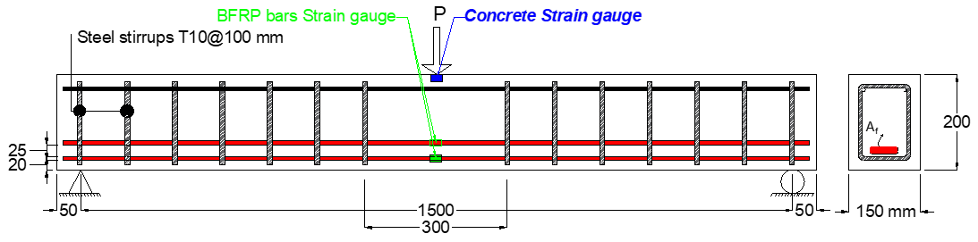
Each RC beam had an overall length of 1600 mm with a clear span of 1500 mm, measured from the center of one support bearing to the other, as illustrated in Figure (1 a and b). The cross-sectional dimensions were kept constant across all specimens, with a width of 150 mm and a total depth of 200 mm, forming a standard rectangular section (refer to Figure 2 a and b).

(a) Group G1 – beams reinforced with conventional steel bars
(b) Group G2 – beams reinforced with BFRP bars
Fig. 1. Schematic and details of the tested RC beams

(a) Reinforced with steel bars (G1)

(b) Reinforced with BFRP bars (G2)
Fig. 2. Cross-sectional view of the proposed beam
As presented in Figure (3), G1 beams were reinforced in the top compression zone with D6 mm steel bars and in the tension zone with either four D12 mm or four D10 mm steel bars arranged in two layers, with additional side bars for symmetry. Shear reinforcement consisted of D10 mm stirrups spaced at 100 mm along the beam. G2 employed the same reinforcement layout, but all steel bars were replaced with D10 mm and D12 mm BFRP bars in both tension and compression zones. This configuration ensured comparable structural detailing between steel and BFRP beams for consistent experimental comparison.

Fig 3. Reinforcement cages in molds
The mechanical properties of the steel and BFRP reinforcements used in this study are summarized in Table 2. The steel bars conform to ASTM A615 standards, with the 10 mm bars additionally meeting ASTM A82 requirements, while the BFRP bars were characterized according to the manufacturer’s specifications.
Table 2. Mechanical properties of steel and BFRP reinforcement
|
Material |
Diameter (mm) |
Tensile Strength (MPa) |
Yield Strength (MPa) |
Modulus of Elasticity (GPa) |
Elongation (%) |
Bend Test Result |
|
Steel |
12 |
658-660 |
448-482 |
~200 |
10.5-11.5 |
Pass |
|
Steel |
10 |
662-663 |
451-487 |
~200 |
11.0-12.0 |
Pass |
|
Steel |
6 |
570-601 |
≥485 |
~200 |
3.3-5.0 |
No visual cracks |
|
BFRP |
12 |
≥900 |
– |
50 |
2.5-3.2 |
– |
|
BFRP |
10 |
≥950 |
– |
55 |
2.5-3.2 |
– |
2.2 Concrete mix
The concrete mix utilized for casting the RC beams was proportioned to achieve a target 28-day compressive strength of 39.8 MPa, reflecting a typical design strength suitable for medium-strength structural applications. The mix design was developed using conventional materials, adhering to standard practices for structural concrete production. The proportions were determined by weight, ensuring appropriate workability, strength development and durability under standard curing conditions. The concrete specimens used in this study consisted of both cubes (150 × 150 × 150 mm) and cylinders (150 mm diameter × 300 mm height) for compressive strength tests. The cement used was Ordinary Portland Cement (OPC) Type I, locally produced by Lafarge (Taslouja), meeting Iraqi Specification No. 5/2019. The fine aggregate was natural river sand with a fineness modulus of 2.95 (Zone II) and SO₃ content of 0.36%, while the coarse aggregate was crushed stone with a nominal size of 5–19 mm and sulfate content of 0.091%, both conforming to IQS 45/1984. A superplasticizer (carboxylate-based) was used to enhance workability and maintain the target water-cement ratio. Details of the concrete-mix composition are presented in Table 3.
Table 3. Concrete mix proportions used in the current study
|
Component |
Cement |
Fine Aggregate |
Coarse Aggregate |
Water |
Superplasticizer |
Slump |
w/c |
|
Quantity |
400 kg/m³ |
700 kg/m³ |
1200 kg/m³ |
180 liters/m³ |
2.8 (0.7) % |
75-100 mm |
0.41 |
The concrete mix was designed with a water-cement ratio (w/c) of 0.41 to balance strength, durability and workability while minimizing permeability. Materials were proportioned by weight and mixed in a rotary drum mixer to achieve uniform consistency, with a target slump of 75-100 mm ensuring adequate workability for casting and vibration. The fresh concrete was placed in two layers within beam molds and compacted using an internal vibrator to eliminate voids and ensure complete reinforcement encapsulation (Figure 4a). After 24 hours of ambient curing, the specimens were demolded (Figure 4b) and transferred to a water tank at 20°C for 28 days to promote full hydration and achieve the desired compressive strength. Finally, all beams were inspected for surface defects and only those meeting quality requirements were retained for flexural testing.
 |
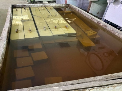 |
Fig. 4. Specimen’s casting and curing
2.3 Test setup and procedures
The experimental program was conducted at the Structural Engineering Laboratory of Mustansiriyah University, as presented in Figure (5), using a 1600 kN hydraulic Universal Testing Machine (UTM) to evaluate the flexural behavior of reinforced concrete beams. Each beam, simply supported over a 1400 mm span, was subjected to a monotonic mid-span point load through a 50 mm steel rod. Instrumentation included concrete and reinforcement strain gauges, three LVDTs for deflection measurements and a calibrated load cell integrated with the UTM. All devices were connected to a LabVIEW-based data acquisition system operating at 10 Hz. Loading was applied at a constant rate of 1 kN/s until failure, defined by dominant flexural cracking, significant loss of capacity, or rupture. Crack development and failure modes were visually documented, while equipment calibration and identical testing conditions ensured reliability and repeatability of the results.
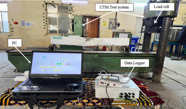
Fig. 5. Experimental test setup and instrumentation details
3 Results and discussion
3.1 Experimental results
3.1.1 Reinforcement strain
The experimental results in Figure (6) illustrate the contrasting behavior of steel- and BFRP-reinforced beams under flexural loading. For the steel-reinforced beams (G1), the peak reinforcement strains ranged from 1300 µε for 4S10 to 1650 µε for 2S12, reflecting the ductile nature of steel reinforcement. Beams with higher steel ratios exhibited lower strains, indicating earlier engagement of the reinforcement and more effective stress transfer to the surrounding concrete. The failure mode in these beams was ductile, characterized by steel yielding followed by concrete crushing, accompanied by significant deflections and crack development.
In comparison, the BFRP-reinforced beams (G2) exhibited substantially higher reinforcement strains, ranging from 2800 µε for 4BF10 to 3400 µε for 2BF12, nearly double those observed in the steel beams. This behavior is consistent with the linear-elastic nature of BFRP bars, which do not yield prior to failure. The failure of BFRP beams was primarily brittle, controlled by concrete crushing rather than bar rupture. Notably, increasing the BFRP reinforcement ratio led to higher ultimate loads while slightly reducing peak strains, as seen in 4BF12, which achieved 118.2 kN at 2950 µε.
The reinforcement strain data highlights that while BFRP-reinforced beams can sustain higher loads compared to steel beams, they do so with reduced ductility. The observed trends emphasize the need for careful design consideration of BFRP beams, particularly with respect to serviceability limits, including deflection and crack control, to balance load capacity with structural performance.
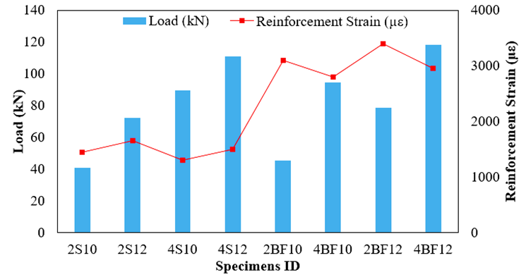
Fig. 6. Reinforcement strain of specimens
3.1.2 Concrete strain
The measured concrete strains, presented in Figure (7), at mid-span provide valuable insight into the flexural performance and failure mechanisms of the tested RC beams. For the steel-reinforced beams (G1), the peak concrete strains ranged from 950 µε in 2S10 to 1900 µε in 4S12. These values increased with both the applied load and the steel reinforcement ratio, reflecting effective stress transfer from the yielding steel to the surrounding concrete. The gradual increase in concrete strain confirms the ductile flexural behavior observed experimentally, where steel yielding preceded concrete crushing. The largest strain in 4S12 coincided with the highest ultimate load (110.966 kN), indicating the synergistic interaction between steel reinforcement and concrete in resisting bending moments.
For the BFRP-reinforced beams (G2), concrete strains were generally higher than in the steel beams at comparable load levels, ranging from 1400 µε in 2BF10 to 2100 µε in 4BF12. This trend reflects the linear-elastic behavior of BFRP bars, which do not yield, thereby transferring larger strains to the concrete until ultimate failure occurs. Notably, 2BF12 exhibited a moderate ultimate load (77.8 kN) but a concrete strain equal to 4S10 (1600 µε), indicating that BFRP-reinforced beams experience higher strain concentrations in the concrete despite comparable loads. The highest concrete strain, observed in 4BF12 (2100 µε), corresponded with the maximum load in the BFRP group (118.5 kN), highlighting that concrete crushing dominated the ultimate failure.
Overall, the concrete strain data confirm that while steel-reinforced beams rely on steel yielding for ductility, BFRP-reinforced beams transmit more stress to the concrete, resulting in higher concrete strains and more brittle behavior. These findings underscore the importance of carefully considering concrete strain limits in BFRP beam design, particularly for serviceability and ultimate performance.
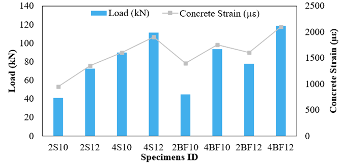
Fig. 7. Concrete strain of specimens
3.1.3 Time to failure and ultimate load capacity
The progression of applied load with time, divided into 30-second intervals up to failure, provides valuable insight into the flexural response and ductility of both steel- and BFRP-reinforced beams. As presented in Figure (8), steel-reinforced beams (G1) exhibited a relatively gradual increase in load during the initial stages, reflecting the progressive engagement of the reinforcement and concrete. For instance, 2S10 and 2S12 reached approximately 70-75% of their ultimate loads by 240 s, while the final 60 s saw slower increments leading to ultimate failure, highlighting their ductile behavior and energy dissipation capacity.
In contrast, BFRP-reinforced beams (G2) demonstrated a distinct load-time pattern. Early-stage load increments were moderate, but the majority of the load was mobilized in the latter half of the test, consistent with the linear-elastic behavior of BFRP bars and the lack of yielding. Beams such as 4BF12 and 4BF10 reached 80-90% of their ultimate loads between 210-270 s, with sudden failure occurring shortly afterward, emphasizing their brittle nature. Despite achieving comparable or higher ultimate loads than steel beams, BFRP beams exhibited larger deflections and concentrated strain, consistent with their lower initial stiffness and reduced ductility.
The time-load analysis confirms that steel beams provide controlled, gradual load progression, ductility and delayed failure, while BFRP beams mobilize high loads rapidly near the end of the test, resulting in brittle failure. These trends reinforce the need to account for serviceability limits and deflection control when designing with BFRP reinforcement, even when ultimate strength is comparable or higher than conventional steel-reinforced beams.
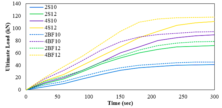
Fig. 8. Time to failure and ultimate load of tested specimens
3.1.4 Mid-Span deflection analysis
The mid-span deflection measurements (Figure 9) provide a clear indication of the stiffness and ductility of the tested RC beams. For the steel-reinforced beams (Group 1), the deflections ranged from 6.8 mm for 2S10 to 11.2 mm for 4S12, increasing consistently with both applied load and reinforcement ratio. This trend reflects the progressive engagement of steel reinforcement and concrete in resisting bending moments. The relatively moderate deflections, together with the observed reinforcement and concrete strains, confirm ductile flexural behavior where steel yielding occurs prior to concrete crushing.
In contrast, the BFRP-reinforced beams (Group 2) exhibited substantially larger mid-span deflections, ranging from 12.5 mm for 2BF10 to 17.5 mm for 4BF12, despite having comparable or higher ultimate loads than their steel counterparts. The larger deflections in BFRP beams are attributed to the linear-elastic behavior of the BFRP bars, which do not yield, resulting in greater strain transfer to the concrete and reduced overall stiffness. For example, 4BF12, which achieved the highest ultimate load (118.2 kN), showed the largest deflection (17.5 mm), highlighting the trade-off between strength and serviceability in BFRP-reinforced beams.
Overall, the deflection data, when combined with the reinforcement and concrete strain results, illustrate the fundamental differences in structural performance between steel and BFRP beams. Steel beams provide ductility and controlled deflections through yielding, whereas BFRP beams, while capable of higher ultimate loads, exhibit increased deflections and reduced ductility, emphasizing the need for careful design consideration in serviceability and safety assessment.
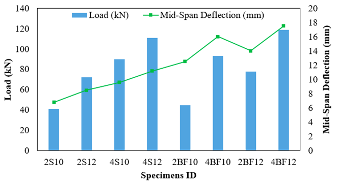
Fig. 9. Mid-span deflection load of beam specimens
3.2 Theoretical investigation
A theoretical investigation was conducted based on the guidelines provided in ACI 440.2R-08 to evaluate the flexural capacity of concrete beams reinforced with continuous basalt fiber-reinforced polymer (BFRP) bars as a replacement for traditional steel reinforcement. The analysis utilized the average compressive strength of concrete obtained through laboratory testing, along with the tensile properties of the BFRP bars as provided by the manufacturer.
It is important to note that ACI 440.2R-08 does not explicitly define an environmental reduction factor for BFRP reinforcement. However, due to the comparable manufacturing processes, mechanical properties and durability characteristics of BFRP and glass fiber-reinforced polymer (GFRP), a reduction factor of 0.75, consistent with that prescribed for GFRP in ACI 440.2R-08, is proposed for BFRP in this study. This assumption is supported by manufacturer data presented in Table 2 and by findings from relevant literature [21,22], providing a rational basis for adopting this value in structural design involving BFRP reinforcement.
The design methodology aligns with the principles outlined in ACI 440.2R-08 and includes the following steps:
1) The design tensile strength and design rupture strain of the FRP material are determined using:
| $f_{fu} = C_E \times f_{fu}^{*}$ | (1) |
| $\varepsilon_{fu} = C_E \times \varepsilon_{fu}^{*}$ | (2) |
Where, $f_{fu}$ = The calculated ultimate tensile strength of fiber-reinforced polymer (FRP) materials used in structural design; $f_{fu}^{*}$ = The ultimate tensile strength of FRP as specified by the manufacturer based on material testing; and $C_{E}$: A coefficient that accounts for the reduction in FRP strength due to environmental exposure over time. $C_{E} = 0.75$ suggested value for BFRP as mentioned in (Table 9.1-ACI 440.2R-08 guidelines)
2) Concrete properties according to ACI 318M-11
| $$\beta_{1} = 0.85 E_{c} = 4700\sqrt{f_{c}'}$$ | (3) |
Where, $\beta_{1}$ : Equivalent stress block depth factor; and $E_{c}$: Modulus of elasticity of concrete.
3) Strain at the Concrete Soffit ($\varepsilon_{bi}$)
| $\varepsilon_{fe} = 0.003 \left( \frac{d_f - c}{c} \right)$ | (4) |
4) Bond-dependent coefficient
| $k_m = 0.7$ |
5) Initial Assumption for neutral axis depth (c)
| $C_{\text{initial}} = 0.2 d$ | (5) |
6) Strain calculations
- Effective strain in FRP at failure:
| $\varepsilon_{fe} = 0.003 \left( \frac{d_f - c}{c} \right) \le k_m \, \varepsilon_{fe}$ | (6) |
- Concrete strain at the compression fiber:
| $\varepsilon_{c} = (\varepsilon_{fd} + \varepsilon_{bi}) \, 0.003 \left( \frac{c}{d_f - c} \right) \le k_m \, \varepsilon_{fe}$ | (7) |
- Steel reinforcement strain:
| $\varepsilon_{e} = 0.003 \left( \frac{d_f - c}{c} \right) \le k_m \, \varepsilon_{fd}$ | (8) |
7) Stress calculations
| - Steel stress: | $f_{s} = E_{s} \times \varepsilon_{s} \le f_{y}$ | (9) |
| - FRP stress: | $f_{fe} = E_{f} \times \varepsilon_{fe}$ | (10) |
8) Calculate the inertial force and verify the equilibrium
| $c = \frac{A f}{\beta_{1} f_{c}' b}$ | (11) |
9) Adjust the value of $C$ iteratively until equilibrium is satisfied between internal forces and external moments.
10) Computing the nominal flexure capacity (Mn)
| $M_n = A_f \times f_s \times \left( d_f - \frac{\beta_1 c}{2} \right)$ | (12) |
| $M_n = A_f \times f_{fe} \times \left( d_f - \frac{\beta_1 c}{2} \right)$ | (13) |
The comparison, in Table (4) and Figure (10), between the ACI 440.2R-08 predicted flexural capacities and the experimentally measured ultimate loads demonstrates good agreement across all tested beams. For the steel-reinforced beams (G1), the predicted capacities were slightly lower than the experimental results, with ACI/Experimental ratios ranging from 0.94 for 2S10 to 0.97 for the larger beams (2S12, 4S10, 4S12). This minor underestimation is consistent with the conservative nature of ACI design provisions, which aim to ensure safety while accounting for variability in material properties and construction practices. The close agreement indicates that the ACI approach reliably captures the flexural behavior of steel-reinforced concrete beams, including the influence of reinforcement ratios on ultimate capacity.
For the BFRP-reinforced beams (G2), the predicted values were also slightly conservative, with ACI/Experimental ratios ranging from 0.93 for 2BF10 to 0.97 for 4BF12. The results confirm that the ACI 440.2R-08 design methodology provides a reasonable estimation of ultimate load for BFRP-reinforced beams, even though BFRP exhibits linear-elastic behavior until failure. Minor deviations are attributed to the higher deflections and strain levels observed in BFRP beams, which are not fully captured in the simplified ACI prediction equations.
Overall, the comparison highlights that the ACI 440.2R-08 design equations offer a safe and reliable tool for predicting ultimate flexural capacity in both steel- and BFRP-reinforced beams. The consistent underestimation also emphasizes the importance of complementing code-based predictions with experimental validation when dealing with novel reinforcement materials like BFRP, particularly in applications where serviceability and ductility are critical.
Table 4. Comparison of ACI 440.2R-08 predictions and experimental results for beam specimens
|
Group |
Specimen |
ACI Prediction (kN) |
Experimental (kN) |
ACI/Exp |
|
(1) |
2S10 |
38.50 |
40.86 |
0.94 |
|
2S12 |
69.98 |
72.19 |
0.97 |
|
|
4S10 |
87.01 |
89.70 |
0.97 |
|
|
4S12 |
107.96 |
110.96 |
0.97 |
|
|
(2) |
2BF10 |
42.03 |
45.21 |
0.93 |
|
4BF10 |
89.97 |
94.52 |
0.95 |
|
|
2BF12 |
74.95 |
78.64 |
0.95 |
|
|
4BF12 |
115.04 |
118.22 |
0.97 |
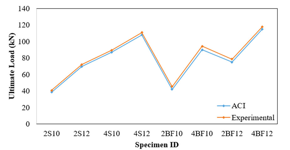
Fig. 10. Experimental and theoretical ultimate load of tested beam specimens
The flexural performance parameters summarized in Table 5 provide a comprehensive comparison of steel- and BFRP-reinforced concrete beams, highlighting key differences in stiffness, load capacity, deflection and energy dissipation. Steel beams (G1) exhibited the highest initial stiffness, with 4S12 reaching 9.908 kN/mm, serving as the reference for normalized parameters. Their ultimate loads ranged from 40.867 kN (2S10) to 110.966 kN (4S12), with ductile behavior reflected in moderate deflections (6.8-11.2 mm) and energy dissipation values (μ) increasing proportionally with reinforcement ratio. The k/k₀, Pu/P₀ and Δ/Δ₀ ratios demonstrate that increasing steel content enhances both strength and stiffness while maintaining controlled ductility.
In contrast, BFRP-reinforced beams (G2) showed significantly lower initial stiffness, from 3.616 kN/mm (2BF10) to 6.754 kN/mm (4BF12), reflecting the lower modulus of elasticity of BFRP bars. Despite this, BFRP beams achieved comparable or higher ultimate loads, ranging from 45.2 kN to 118.2 kN and exhibited larger deflections (12.5-17.5 mm) due to their linear-elastic behavior. The normalized energy dissipation values (μ/μ₀) indicate that BFRP beams, particularly 4BF12 (1.666), can store more energy before failure compared to steel beams, although this comes with reduced stiffness and increased service deflections.
The results demonstrate the fundamental trade-offs between steel and BFRP reinforcement: steel provides higher initial stiffness and ductility, while BFRP allows for higher ultimate loads and energy dissipation at the expense of larger deflections. These results emphasize the need to carefully balance strength, stiffness and serviceability in the design of BFRP-reinforced beams.
Table 5. Flexural performance parameters for steel and BFRB reinforced concrete beams
|
Beam |
Initial Stiffness k (kN/mm) |
k/kcontrol |
Max. Load Pu (kN) |
Pu/Pucontrol |
Max. Deflection Δ (mm) |
Δ/Δcontrol |
Ductility μ |
μ/μcontrol |
|
4S12 |
9.908 |
1.000 |
110.966 |
1.000 |
11.2 |
1.000 |
1242.819 |
1.000 |
|
2S12 |
8.494 |
0.857 |
72.198 |
0.651 |
8.5 |
0.759 |
613.683 |
0.494 |
|
4S10 |
9.344 |
0.943 |
89.703 |
0.808 |
9.6 |
0.857 |
861.149 |
0.693 |
|
2S10 |
6.01 |
0.607 |
40.867 |
0.368 |
6.8 |
0.607 |
277.896 |
0.224 |
|
2BF10 |
3.616 |
0.365 |
45.211 |
0.408 |
12.5 |
1.116 |
565.221 |
0.455 |
|
4BF10 |
5.906 |
0.596 |
94.521 |
0.852 |
16.1 |
1.429 |
1512.212 |
1.217 |
|
2BF12 |
5.614 |
0.567 |
78.612 |
0.708 |
14.2 |
1.251 |
1100.412 |
0.886 |
|
4BF12 |
6.754 |
0.682 |
118.211 |
1.065 |
17.5 |
1.563 |
2068.521 |
1.666 |
Figures (11 and 12) compare the theoretical and experimental load–mid-deflection curves for the two group tested specimens. The overall trend of the theoretical curves was in reasonable agreement with the experimental results, particularly in capturing the general shape of the load-deflection response. However, the ultimate load-carrying capacities were overestimated for specimens with a total reinforcement ratio exceeding 1.06%. This discrepancy can be attributed to the assumptions made in the theoretical modeling, where steel or BFRP bars were idealized as fully bonded to the concrete matrix.
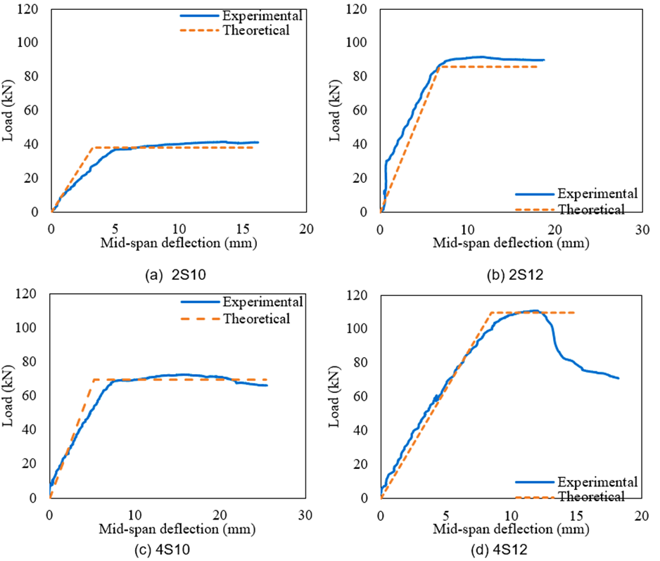
Fig. 11. Comparison of experimental and theoretical load-mid deflection curves for steel reinforced beams (G1)
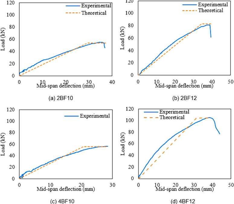
Fig. 12. Comparison of experimental and theoretical load-mid deflection curves for BFRP reinforced beams (G2)
The experimental results, shown in Table (6), demonstrate a clear distinction between steel- and BFRP-reinforced beams, consistent with ACI 440.2R-08 predictions. Steel-reinforced beams (2S10-4S12) exhibited ductile flexural failure, with yielding of steel followed by gradual concrete crushing, allowing for large deflections, crack development and controlled energy dissipation; the highest steel-reinforced beam, 4S12, achieved 110.966 kN while maintaining ductility.
In contrast, BFRP-reinforced beams (2BF10-4BF12) showed brittle failure governed by concrete crushing, as the linear-elastic BFRP bars did not yield, leading to sudden failure after moderate to large deflections. Lower-reinforced BFRP beams exhibited moderate ductility, while higher-reinforced beams, such as 4BF12, reached 118.2 kN but failed abruptly, emphasizing the trade-off between high ultimate load and reduced post-peak deformation.These findings highlight that steel beams provide controlled, ductile behavior, whereas BFRP beams offer higher load capacity at the cost of ductility, confirming the reliability of ACI 440.2R-08 in predicting failure modes for both reinforcement types.
The novelty of the present study lies in the experimental characterization and comparative analysis of RC beams strengthened with BFRP bars, a material that offers high corrosion resistance and long-term durability compared to conventional steel reinforcement. While previous studies have explored FRP or hybrid reinforcements, limited research exists on BFRP as a primary longitudinal reinforcement in RC beams under flexural loading. The core problem addressed is the need for alternative reinforcement materials that mitigate the effects of corrosion and enhance structural longevity, while providing comparable or superior load-carrying capacity and energy absorption. The findings of this study provide a foundation for future research, which could focus on long-term durability under environmental exposure, fatigue behavior under cyclic loading, hybrid BFRP-steel reinforcement systems, and the development of design guidelines or predictive models to optimize the performance of BFRP-reinforced RC structures in practical applications.
Table 6. Experimental and theoretical failure modes of steel- and BFRP-RC beams
|
Specimen ID |
Experimental Failure Mode |
Theoretical Failure Mode |
Key Observations |
|
2S10 |
Ductile Flexural Failure |
Steel Yielding |
Yielded steel, followed by concrete crushing. Large deflection and crack width. |
|
2S12 |
Ductile Flexural Failure |
Steel Yielding |
Yielded steel, followed by concrete crushing. |
|
4S10 |
Ductile Flexural Failure |
Steel Yielding |
Yielded steel, followed by concrete crushing. |
|
4S12 |
Ductile Flexural Failure |
Steel Yielding |
Yielded steel, followed by concrete crushing. Highest load capacity in control group. |
|
2BF10 |
Brittle Flexural Failure |
Concrete Crushing |
No bar yielding; failure controlled by concrete crushing. Moderate deflection. |
|
4BF10 |
Brittle Flexural Failure |
Concrete Crushing |
Concrete crushed before bars reached ultimate strain. Larger load than 2BF10. |
|
2BF12 |
Brittle Flexural Failure |
Concrete Crushing |
Concrete crushing preceded BFRP rupture. Moderate ductility. |
|
4BF12 |
Brittle Flexural Failure |
Concrete Crushing |
Highest load in BFRP group. Sudden failure after concrete crushing. |
3.3 Limitations and future studies
The novelty of the present study lies in the experimental characterization and comparative analysis of RC beams strengthened with BFRP bars, a material that offers high corrosion resistance and long-term durability compared to conventional steel reinforcement. While previous studies have explored FRP or hybrid reinforcements, limited research exists on BFRP as a primary longitudinal reinforcement in RC beams under flexural loading. The core problem addressed is the need for alternative reinforcement materials that mitigate the effects of corrosion and enhance structural longevity, while providing comparable or superior load-carrying capacity and energy absorption.
Despite the comprehensive experimental and analytical investigation presented in this study, several limitations should be noted. First, the number of RC beam specimens tested was limited, which restricts the ability to assess variability and perform extensive statistical analysis. Expanding the sample size in future studies would improve the robustness and generalizability of the findings. Second, the beams were tested under monotonic flexural loading only, whereas real-world structures often experience cyclic, dynamic, or seismic loads. Investigating the behavior of BFRP-reinforced beams under such complex loading conditions would provide valuable insights for practical applications.
Another limitation is the absence of long-term environmental exposure effects. The study did not account for factors such as temperature fluctuations, freeze-thaw cycles, or aggressive chemical environments, which may influence the durability of both BFRP and steel reinforcement. Additionally, all tested beams had identical cross-sectional dimensions and concrete mix proportions. Future research could explore variations in beam geometry, reinforcement ratios, and concrete strengths to evaluate their influence on structural performance and serviceability. While ultimate load capacity and crack behavior were thoroughly analyzed, long-term effects such as deflection, creep, and shrinkage in BFRP-reinforced beams require further investigation.
Future studies may also focus on hybrid reinforcement strategies combining BFRP with other FRP types or steel to optimize ductility, strength, and serviceability. Numerical modeling and finite element simulations of larger structural systems, validated against experimental results, could further advance the design guidelines for BFRP-reinforced concrete. Finally, long-term monitoring and durability studies, including corrosion resistance, fatigue behavior, and fire performance, would help confirm the practical applicability and safety of BFRP as a primary reinforcement in structural concrete. These efforts will contribute to a more complete understanding of BFRP-reinforced systems and support the development of durable and efficient concrete structures.
4 Conclusions
This study investigated the flexural performance of RC beams strengthened with conventional steel and BFRP bars, providing a comprehensive comparison of their mechanical behavior, serviceability and ultimate capacity. The experimental results demonstrated that steel-reinforced beams exhibited ductile flexural failure, characterized by yielding of steel followed by gradual concrete crushing, allowing for controlled deflections, crack development and energy dissipation. In contrast, BFRP-reinforced beams failed in a brittle manner, with failure governed by concrete crushing and linear-elastic behavior of the BFRP bars, resulting in sudden failure after larger deflections and higher strain concentrations in the concrete. The analysis of reinforcement and concrete strains, mid-span deflections and energy dissipation revealed that BFRP-reinforced beams can achieve higher ultimate loads and energy absorption compared to steel beams, despite lower initial stiffness and moderate ductility. Time-to-failure evaluations further highlighted the gradual load progression in steel beams versus the rapid mobilization of load near failure in BFRP beams. Theoretical predictions based on ACI 440.2R-08 were in good agreement with experimental results, with minor conservative underestimations (ACI/Exp ratios 0.93-0.97), confirming the reliability of the design methodology for both steel and BFRP reinforcement.
Finally, the findings emphasize the trade-offs between strength, ductility and serviceability inherent to different reinforcement types: steel reinforcement provides controlled, ductile behavior suitable for serviceability-critical applications, while BFRP reinforcement enables higher ultimate loads and energy storage at the expense of stiffness and post-peak ductility. These insights provide a valuable reference for the design and optimization of RC beams using innovative BFRP reinforcement, highlighting the need for careful consideration of deflection, crack control and load capacity in practical applications.
Acknowledgements
The authors would like to thank the laboratories of the Mustansiriyah University for providing the experimental facilities and technical support needed to complete this study.
References
- Alabtah, F. G., Mahdi, E., & Eliyan, F. F. (2021). The use of fiber reinforced polymeric composites in pipelines: A review. Composite Structures, 276, 114595. https://doi.org/10.1016/j.compstruct.2021.114595.
- Obaydullah, M. (2021). Strengthening of Prestressed Concrete Beams Using Combined Externally Bonded and Prestressed near Surface Mounted Technique (Doctoral dissertation, University of Malaya (Malaysia)). https://doi.org/10.3390/polym8070261
- Effiong, J. U., & Ede, A. N. (2022). Experimental investigation on the strengthening of reinforced concrete beams using externally bonded and near-surface mounted natural fibre reinforced polymer composites-a review. Materials, 15(17), 5848. https://doi.org/10.3390/ma15175848
- Megahed, F. A., Seleem, M. H., Badawy, A. A. M., & Sharaky, I. A. (2023). The flexural response of RC beams strengthened by EB/NSM techniques using FRP and metal materials: a state-of-the-art review. Innovative Infrastructure Solutions, 8(11), 289. https://shorturl.at/zTEuT.
- Kumar, A., Dixit, S., Singh, S., S., Sreenivasa, S., Bains, P. S., & Sharma, R. (2025). Recent developments in the mechanical properties and recycling of fiber‐reinforced polymer composites. Polymer Composites, 46(5), 3883-3908.https://doi.org/10.1002/pc.29261
- Jagadeesh, P., Rangappa, S. M., & Siengchin, S. (2024). Basalt fibers: An environmentally acceptable and sustainable green material for polymer composites. Construction and Building Materials, 436, 136834. https://doi.org/10.1016/j.conbuildmat.2024.136834.
- Abdulhameed, S. S., & Hamza, D. M. (2023). Flexural behavior of reinforced concrete beams strengthened with hybrid steel-FRP reinforcements by using near surface mounted technique. Journal of Applied Engineering Science, 21(3), 758-766. https://doi.org/10.5937/jaes0-39645
- Abulqasim, S. A., Noori, A. Q. N., & Celik, T. (2022). Numerical investigation on flexural behavior of RC beams with large web opening externally strengthened with CFRP laminates under cyclic load: Three-point bending test. Journal of Applied Engineering Science, 20(2), 571-581. https://doi.org/10.5937/jaes0-32985.
- Mensah, C., Wang, Z., Bonsu, A. O., & Liang, W. (2020). Effect of different bond parameters on the mechanical properties of FRP and concrete interface. Polymers, 12(11), 2466. https://doi.org/10.3390/polym12112466
- Barris, C., Baena, M., Jahani, Y., Codina, A., & Torres, L. (2023). Experimental study on flexural cracking and deformation of reinforced-concrete beams strengthened with NSM FRP reinforcement. Journal of Composites for Construction, 27(2), 04023006. https://doi.org/10.1061/JCCOF2.CCENG-390
- Abushanab, A., Alnahhal, W., & Farraj, M. (2022). Experimental and finite element studies on the structural behavior of BFRC continuous beams reinforced with BFRP bars. Composite Structures, 281, 114982. https://doi.org/10.1016/j.compstruct.2021.114982
- Alhoubi, Yazan, Zin Mahaini and Farid Abed. "The flexural performance of BFRP-reinforced UHPC beams compared to steel and GFRP-reinforced beams." Sustainability 14.22 (2022): 15139. https://doi.org/10.3390/su142215139
- Alkhraisha, H., Mhanna, H., Tello, N., & Abed, F. (2020). Serviceability and flexural behavior of concrete beams reinforced with basalt fiber-reinforced polymer (BFRP) bars exposed to harsh conditions. Polymers, 12(9), 2110. https://doi.org/10.3390/polym12092110
- Jing, L., Yin, S. P., & Duan, K. (2019). Analysis of the interface bond property between the concrete and steel bar under textile reinforced concrete confinement. Construction and Building Materials, 224, 447-454. https://doi.org/10.1016/j.conbuildmat.2019.07.102
- Mak, M. W. T., & Lees, J. M. (2022). Bond strength and confinement in reinforced concrete. Construction and Building Materials, 355, 129012. https://doi.org/10.1016/j.conbuildmat.2022.129012
- Harle, S. M. (2024, February). Durability and long-term performance of fiber reinforced polymer (FRP) composites: A review. In Structures (Vol. 60, p. 105881). Elsevier. https://doi.org/10.1016/j.istruc.2024.105881
- Chen, Z., Yu, J., Nong, Y., Yang, Y., Zhang, H., & Tang, Y. (2023). Beyond time: Enhancing corrosion resistance of geopolymer concrete and BFRP bars in seawater. Composite Structures, 322, 117439. https://doi.org/10.1016/j.compstruct.2023.117439
- El-Ghandour, A. A. (2011). Experimental and analytical investigation of CFRP flexural and shear strengthening efficiencies of RC beams. Construction and Building Materials, 25(3), 1419-1429. https://doi.org/10.1016/j.conbuildmat.2010.09.001
- Hadi, M. K., Almamoori, A. H. N., & Naser, F. H. (2024, November). Load capacity of RC members subjected to marine environment and rehabilitated with FRP: State of the art review. In AIP Conference Proceedings (Vol. 3219, No. 1). AIP Publishing. https://doi.org/10.1063/5.0236570.
- Guo, H., Wang, H., Xue, H., Li, H., Li, Y., & Wei, L. (2024). Study on damage deterioration mechanism and service life prediction of hybrid fibre concrete under different salt freezing conditions. Construction and Building Materials, 435, 136688. https://doi.org/10.1016/j.conbuildmat.2024.136688.
- Al-Nsour, R., Abdel-Jaber, M. T., Ashteyat, A., & Shatarat, N. (2023). Flexural repairing of heat damaged reinforced concrete beams using NSM-BFRP bars and NSM-CFRP ropes. Composites Part C: Open Access, 12, 100404. https://doi.org/10.1016/j.jcomc.2023.100404.
- Bunsell, A. R. (Ed.). (2018). Handbook of properties of textile and technical fibres. Woodhead Publishing. 2018, pp. 805–840.
Conflict of Interest Statement
The authors declare that they have no known competing financial or non-financial interests that could have appeared to influence the work reported in this manuscript.
Author Contributions
Data Availability Statement
The datasets generated and/or analyzed during the current study are available from the corresponding author on reasonable request.
Supplementary Materials
This research received no specific grant from any funding agency in the public, commercial, or not-for-profit sectors.