Received: Apr 15, 2026 Accepted: Aug 20, 2026 Available Online: Sep 03, 2026
DOI: 10.5937/jaes0-66515
INFLUENCE OF E6013/E7016 ELECTRODE SEQUENCE ON THE MECHANICAL, MICROSTRUCTURAL, AND CORROSION BEHAVIOUR OF SMAW-WELDED SS400 STEEL
Abstract
Electrode selection and deposition sequence can affect the mechanical, microstructural, and corrosion characteristics of shielded metal arc welding (SMAW) joints. This study investigated four E6013/E7016 root–cap combinations, namely E6013–E6013, E6013–E7016, E7016–E6013, and E7016–E7016, for welding 8 mm SS400 steel using a two-pass single-V-groove joint. The welded joints were evaluated by liquid penetrant testing, tensile testing, Vickers microhardness, optical microscopy with ImageJ-based phase estimation, and potentiodynamic polarization in 3.5 wt. % NaCl solution. No clear surface-breaking cracks were detected. E6013–E6013 produced the highest ultimate tensile strength of 464.37 ± 0.87 MPa, whereas E7016–E7016 exhibited the highest yield strength of 331.47 ± 18.09 MPa. The highest weld-metal hardness was obtained with E7016–E6013 at approximately 205.80 HV0.3. All conditions exhibited ferrite-dominant microstructures, with E7016–E7016 showing the highest weld-metal ferrite fraction of 76.14 ± 4.47%. E7016–E7016 also provided the highest corrosion resistance, with the lowest corrosion rate of 0.00550 mm/year. Overall, E6013–E6013 provided a favourable balance of tensile strength, hardness uniformity, microstructural consistency, and corrosion resistance, while E7016–E7016 exhibited superior corrosion resistance.
Highlights
- E6013–E6013 achieved the highest UTS of 464.37 ± 0.87 MPa.
- E7016–E6013 produced the highest weld-metal hardness of 205.80 HV0.3.
- E7016–E7016 exhibited the best corrosion resistance at 0.00550 mm/year.
Keywords
Content
1 Introduction
Shielded metal arc welding (SMAW) is widely applied to structural and low-carbon steels because of its simple equipment, operational flexibility, and suitability for various fabrication conditions [1]. Weld quality is influenced by welding current, heat input, joint geometry, electrode characteristics, and deposition conditions, which affect the thermal cycle and resulting mechanical and microstructural properties [2]. Similar relationships between SMAW parameters and the mechanical response of low-carbon steels have been reported in welded structural steels [3,4].
Electrode selection is particularly important because differences in coating composition, deposited-metal characteristics, and welding behaviour may alter tensile strength, hardness, and microstructure. The number of passes and electrode type have been shown to affect hardness and microstructural development in SMAW joints [5]. Direct comparison of E6013 and E7016 also indicates that electrode type and welding current influence local hardness and microstructure [6]. Variations in electrode selection have likewise been associated with differences in tensile behaviour and weld-metal characteristics [7,8].
SS400 is a low-carbon structural steel commonly used in construction and general engineering because of its adequate strength and favourable weldability. Previous SMAW studies on SS400 have shown that joint geometry, welding current, and weld-metal composition can modify tensile properties, hardness, and microstructure. [9,10,11]. Similar changes in mechanical behaviour and microstructural characteristics have also been reported for SMAW-welded low-carbon AISI 1020 steel. [12]. These findings indicate that electrode performance depends not only on nominal electrode classification but also on its application and deposition conditions.
Corrosion behaviour is also important for welded carbon steels exposed to chloride-containing environments. Welding produces metallurgical heterogeneity among the base metal (BM), heat-affected zone (HAZ), and weld metal (WM), which may result in different electrochemical responses. Welding parameters have been reported to affect the corrosion rate of welded SS400 steel. [13]. While electrode and current variations can simultaneously influence microstructure, mechanical properties, and corrosion resistance [14]. Other SMAW investigations have also demonstrated that joint configuration and weld-metal characteristics affect corrosion behaviour. [15,16]. Therefore, corrosion testing complements mechanical and microstructural evaluation when assessing overall welded-joint performance.
Non-destructive examination is commonly used to verify weld-surface integrity before destructive testing. Visual and penetrant testing have been applied to assess discontinuities in SMAW-welded low-carbon and structural steels [17,18]. Despite extensive studies on welding current, electrode type, microstructure, mechanical properties, and corrosion behaviour, most investigations have considered these variables separately. Recent studies continue to show that welding process and electrode conditions influence the mechanical and microstructural performance of structural steels [19,20]. However, limited information is available on the sequential use of E6013 and E7016 between the root and cap passes of SS400 steel under identical welding conditions. In particular, the comparative behaviour of E6013–E6013, E6013–E7016, E7016–E6013, and E7016–E7016 combinations has not been widely evaluated by integrating surface integrity, tensile properties, hardness distribution, microstructure, and corrosion resistance. The present study therefore focuses on the root–cap electrode sequence as the principal experimental variable and integrates these responses within a single comparative framework. This approach provides application-oriented insight into how electrode deposition sequence affects the overall performance of SMAW-welded SS400 joints. Accordingly, the four electrode sequences were evaluated using liquid penetrant testing, tensile testing, Vickers microhardness measurements, optical microstructural analysis, and potentiodynamic polarization in 3.5 wt.% NaCl solution.
2 Materials and methods
2.1 Materials and chemical composition
Optical emission spectroscopy (OES) identified the investigated material as low-carbon steel, with a chemical composition of 0.17 wt.% C, 0.694 wt.% Si, 0.256 wt.% Mn, 0.003 wt.% P, 0.016 wt.% S, and 98.06 wt.% Fe. Its relatively low carbon content provides favourable weldability, making the material suitable for the SMAW process.
2.2 SMAW welding procedure
SS400 steel plates measuring 100 mm × 300 mm × 8 mm were prepared as four welded joints from eight plates. A single-sided V-groove butt joint was used in accordance with AWS D1.1/D1.1M. [21], with a 30° bevel on each plate edge, giving a 60° included groove angle, 2 mm root face, and 2 mm root gap, as shown in Fig. 1. The same joint geometry was maintained for all specimens to minimise the influence of variables other than the electrode combination.
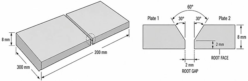
Fig. 1. Dimensions of the SS400 plate specimen and geometry of the single-V-groove butt joint (all dimensions in mm)
Welding was performed using the Shielded Metal Arc Welding (SMAW) process in the 1G flat position by a qualified welder. SS400 steel plates measuring 300 mm × 100 mm × 8 mm were prepared with a single-V-groove butt joint having a 60° groove angle, 2 mm root gap, and 2 mm root face. Before welding, the joint surfaces were cleaned, aligned, and clamped to maintain the specified geometry.
AWS A5.1 E6013 and E7016 electrodes with a diameter of 3.2 mm were used with DCEP polarity at 110 A, 25 V, and a travel speed of 120 mm/min. Each joint was deposited in two passes comprising a root pass and a cap pass. The electrode combinations were designated according to the root–cap sequence; for example, E6013–E7016 represents an E6013 root pass followed by an E7016 cap pass. The electrode angle, arc length, and interpass temperature were maintained at 70–80°, 1.0–2.5 mm, and 100–150 °C, respectively. Before welding, the joint surfaces were ground, cleaned, aligned, and clamped to maintain the specified joint geometry. Identical nominal welding parameters were applied to all specimens to minimise the influence of variables other than the electrode sequence. The complete welding parameters are presented in Table 1.
Table 1. Welding parameters
|
Variable |
Record |
|
Code / Standard |
AWS D1.1/D1.1M |
|
Welding process |
SMAW |
|
Welding position |
1G (Flat Position) |
|
Joint design |
Single-V-groove butt joint |
|
Material |
SS400 |
|
Thickness |
8 mm |
|
Electrode |
AWS A5.1 E6013 and E7016, Ø3.2 mm |
|
Welding polarity |
DCEP |
|
Number of passes |
2 (root and cap) |
|
Welding current |
110 A |
|
Arc voltage |
25 V |
|
Travel speed |
120 mm/min |
|
Electrode angle |
70–80° |
|
Arc length |
1.0–2.5 mm |
|
Interpass temperature |
100–150 °C |
|
Welding efficiency |
0.8 |
|
Arc energy |
1.375 kJ/mm |
|
Calculated heat input |
1.100 kJ/mm |
|
Inspection |
Visual inspection and liquid penetrant testing |
The calculated heat input was determined using Eq. (1), adopting a thermal efficiency factor of η = 0.8 for the Shielded Metal Arc Welding (SMAW) process in accordance with BS EN 1011-1:2009 [22].
where HI is the heat input (kJ/mm), η is the SMAW thermal efficiency (0.8), V is the arc voltage, I is the welding current, and S is the welding speed. At 25 V, 110 A, and 120 mm/min, the arc energy was 1.375 kJ/mm, and the net heat input was 1.100 kJ/mm. Identical welding parameters were used for all E6013–E7016 combinations to isolate the effects of electrode type and deposition sequence.
After welding, the joints were visually inspected and examined by liquid penetrant testing using Magnaflux SKC-S cleaner, SKL-SP2 penetrant, and SKD-S2 developer. Penetrant and developer dwell times were 7–10 min, and visible indications were evaluated under white light with reference to EN ISO 3452-1:2021 and ISO 23277:2015.
2.3 Tensile testing
Transverse tensile specimens were prepared with the weld centred in the gauge section and tested according to ASTM E8/E8M using a 100 kN universal testing machine at a crosshead speed of 1 mm/min. Three specimens were tested for each welding condition. Yield strength, ultimate tensile strength, and elongation were reported as mean ± standard deviation, and the fracture location was recorded as BM, HAZ, or WM.
2.4 Hardness testing
Vickers microhardness testing was performed according to ASTM E92 using a 300 gf load (HV0.3) and a dwell time of 15 s. Seventeen indentations were made at 1 mm intervals along a horizontal traverse from −8 to +8 mm, with the weld centre defined as 0 mm. The measurement points covered the BM, HAZ, and WM regions to evaluate hardness variations across the welded joint.
2.5 Metallographic preparation and microstructural analysis
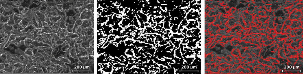
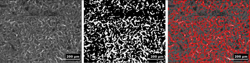
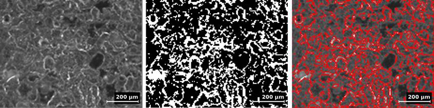
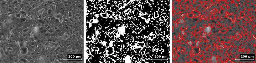
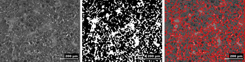
Transverse sections covering the BM, HAZ, and WM were ground with 240–5000 grit papers, polished with 1 μm alumina, and etched with 2–5% Nital in accordance with ASTM E407. Three non-overlapping micrographs per region and welding condition were acquired at 50× magnification with a 200 μm scale bar. The images were analysed semi-quantitatively using ImageJ 1.54. After calibration, each image was converted to 8-bit grayscale and segmented using the Default automatic threshold, with the lighter and darker regions assigned to ferrite and pearlite, respectively. The estimated phase-area fractions were calculated from the segmented pixel areas and reported as mean ± standard deviation from three fields.
2.6 Corrosion testing
Corrosion behaviour was evaluated by potentiodynamic polarization using a three-electrode electrochemical cell. The BM reference specimen and the capping surfaces of the welded specimens were tested in 3.5 wt.% NaCl solution. Corrosion potential (E₍corr₎) and corrosion current density (i₍corr₎) were determined by Tafel extrapolation, and the corrosion rate was calculated according to ASTM G102-23 and expressed in mm/year.
3 Results and discussion
3.1 Non-destructive testing

Fig. 2. Visual inspection and liquid penetrant testing results of SMAW joints with electrode combinations: (a) E6013–E6013, (b) E6013–E7016, (c) E7016–E7016, and (d) E7016–E6013
Visual inspection and penetrant testing showed generally continuous weld surfaces for all electrode combinations. The 6013–6013 and 7016–6013 joints exhibited relatively uniform penetrant patterns, whereas 6013–7016 and 7016–7016 showed several localised irregular indications along the weld line. No clear continuous linear indications associated with surface-breaking cracks were observed. Similar applications of visual and penetrant inspection for detecting surface discontinuities in welded joints have been reported by [18,23]. Previous studies have applied penetrant testing to E7016 SMAW joints and combined visual and penetrant inspection for weld-quality assessment [10,19]. Overall, the results indicate acceptable surface integrity, although the localised indications should be assessed according to the applicable acceptance criteria.
3.2 Tensile testing
Tensile testing was performed to evaluate the mechanical response of SS400 joints produced using different E6013/E7016 electrode sequences. UTS, YS, and elongation were reported as mean ± standard deviation from three specimens for each condition.

Fig. 3. Tensile specimens after testing for the BM and SMAW-welded joints with different E6013/E7016 electrode combinations
Table 2. Tensile properties of the BM and SMAW-welded SS400 joints with different electrode combinations
|
Electrode combination |
UTS (MPa) |
YS (MPa) |
Elongation (%) |
|
BM SS400 |
465.50 ± 7.91 |
331.70 ± 4.67 |
38 ± 2 |
|
E6013–E6013 |
464.37 ± 0.87 |
326.08 ± 4.97 |
24 ± 3 |
|
E6013–E7016 |
462.82 ± 0.38 |
324.42 ± 3.63 |
24 ± 1 |
|
E7016–E6013 |
461.19 ± 2.06 |
315.60 ± 4.10 |
28 ± 2 |
|
E7016–E7016 |
459.43 ± 0.92 |
331.47 ± 18.09 |
24 ± 0 |
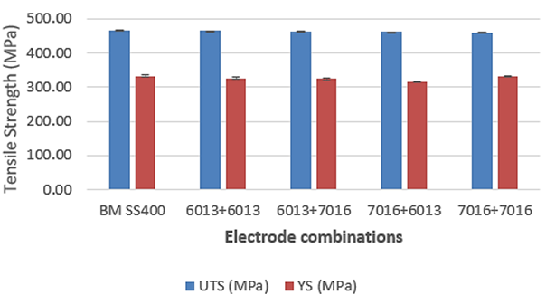
Fig. 4. Ultimate tensile strength and yield strength of the base metal and SMAW-welded SS400 joints with different electrode combinations. Error bars represent the standard deviation of three specimens
Based on Table 2 and Fig. 4, the BM exhibited a UTS of 465.50 ± 7.91 MPa. Among the welded joints, E6013–E6013 produced the highest UTS (464.37 ± 0.87 MPa), followed by E6013–E7016, E7016–E6013, and E7016–E7016. The narrow UTS range of only 4.94 MPa indicates that all electrode combinations provided relatively comparable tensile strength. Similar effects of electrode type and welding conditions on the tensile behaviour of SMAW joints have been reported by [7,24]. The small differences observed among the present joints may be related to variations in electrode sequence, weld-metal characteristics, thermal cycle, and the resulting microstructure. For YS, the BM reached 331.70 ± 4.67 MPa, while E7016–E7016 showed the highest welded-joint value of 331.47 ± 18.09 MPa. However, its relatively large standard deviation indicates greater variation among the tested specimens, whereas E6013–E7016 exhibited the lowest YS scatter. Comparable relationships between welding parameters, electrode characteristics, and tensile response have also been reported [25,9] Overall, the electrode combinations produced only minor differences in UTS, whereas YS showed greater sensitivity to local weld-metal characteristics, thermal history, and microstructural heterogeneity.
3.3 Hardness testing
Vickers microhardness testing was performed to evaluate hardness variations across the BM, HAZ, and WM regions for the different E6013/E7016 electrode sequences.

Fig. 5. Vickers microhardness profiles across the BM–HAZ–WM–HAZ–BM regions of SMAW-welded SS400 joints with different electrode combinations
Figure 5 shows the HV0.3 profiles across the BM–HAZ–WM–HAZ–BM regions for the different electrode combinations. In all joints, hardness generally increased toward the weld centre and decreased toward the opposite BM. The highest WM hardness, approximately 200–205 HV0.3, was observed for E7016–E6013 and E7016–E7016, while E6013–E6013 exhibited the lowest and most uniform profile. E6013–E7016 showed intermediate behaviour. Similar effects of electrode type and welding parameters on weld hardness have been reported for E6013- and E7016-based SMAW joints [26]. Hardness variations across welded regions have also been associated with welding-induced thermal and microstructural changes [4], while relationships between local microstructure and hardness have been demonstrated in SMAW-welded structural low-carbon steel [27]. Overall, the electrode combination mainly affected the WM and adjacent HAZ regions.
The higher WM hardness of E7016–E6013 may be associated with differences in deposited weld-metal characteristics and the thermal history generated by the root–cap electrode sequence. Because the nominal welding current, voltage, travel speed, and heat input were maintained constant, the observed hardness variation is more reasonably attributed to electrode-related characteristics and local microstructural evolution rather than changes in nominal heat input. In contrast, E6013–E6013 produced the highest welded-joint UTS despite exhibiting the lowest and most uniform hardness profile, indicating that local WM hardness alone did not control the overall tensile response. The tensile strength reflects the mechanical behaviour of the entire BM–HAZ–WM system and may therefore depend on microstructural uniformity and local heterogeneity across the joint. Differences in electrode coating characteristics and diffusible-hydrogen behaviour may also contribute to the weld-metal response; however, diffusible hydrogen and cooling rate were not measured in the present study.
3.4 Microstructural analysis
3.4.1 Microstructures of 6013-6013
|
Grayscale |
Threshold |
Overlay |
Fig. 6. Optical micrograph and ImageJ segmentation of the base metal for the E6013–E6013 electrode combination at 50× magnification; scale bar = 200 μm
|
Grayscale |
Threshold |
Overlay |
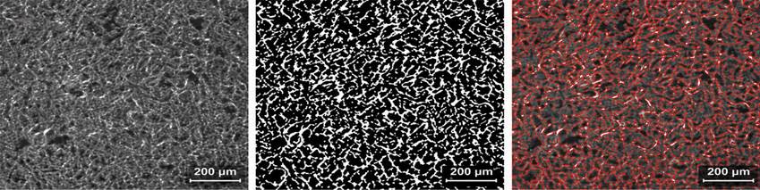
Fig. 7. Optical micrograph and ImageJ segmentation of the heat-affected zone for the E6013–E6013 electrode combination at 50× magnification; scale bar = 200 μm
|
Grayscale |
Threshold |
Overlay |
Fig. 8. Optical micrograph and ImageJ segmentation of the weld metal for the E6013–E6013 electrode combination at 50× magnification; scale bar = 200 μm
3.4.2 Microstructures of 6013-7016
|
Grayscale |
Threshold |
Overlay |
Fig. 9. Optical micrograph and ImageJ segmentation of the base metal for the E6013–E7016 electrode combination at 50× magnification; scale bar = 200 μm
|
Grayscale |
Threshold |
Overlay |
Fig. 10. Optical micrograph and ImageJ segmentation of the heat-affected zone for the E6013–E7016 electrode combination at 50× magnification; scale bar = 200 μm
|
Grayscale |
Threshold |
Overlay |
Fig. 11. Optical micrograph and ImageJ segmentation of the weld metal for the E6013–E7016 electrode combination at 50× magnification; scale bar = 200 μm
3.4.3 Microstructures of 7016-6013
|
Grayscale |
Threshold |
Overlay |
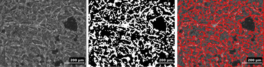
Fig. 12. Optical micrograph and ImageJ segmentation of the base metal for the E7016–E6013 electrode combination at 50× magnification; scale bar = 200 μm
|
Grayscale |
Threshold |
Overlay |
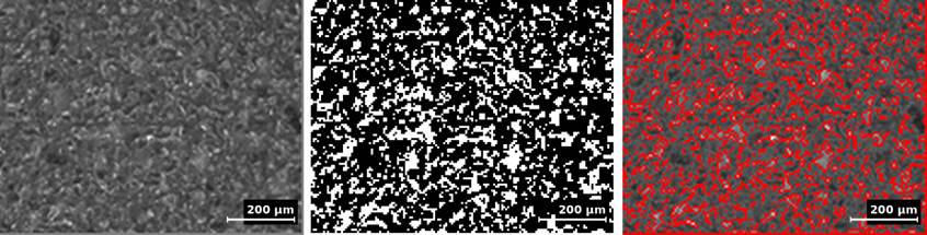
Fig. 13. Optical micrograph and ImageJ segmentation of the heat-affected zone for the E7016–E6013 electrode combination at 50× magnification; scale bar = 200 μm
|
Grayscale |
Threshold |
Overlay |
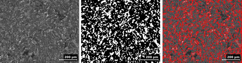
Fig. 14. Optical micrograph and ImageJ segmentation of the weld metal for the E7016–E6013 electrode combination at 50× magnification; scale bar = 200 μm
3.4.4 Microstructures of 7016-7016
|
Grayscale |
Threshold |
Overlay |
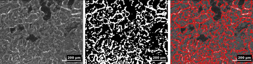
Fig. 15. Optical micrograph and ImageJ segmentation of the base metal for the E7016–E7016 electrode combination at 50× magnification; scale bar = 200 μm
|
Grayscale |
Threshold |
Overlay |
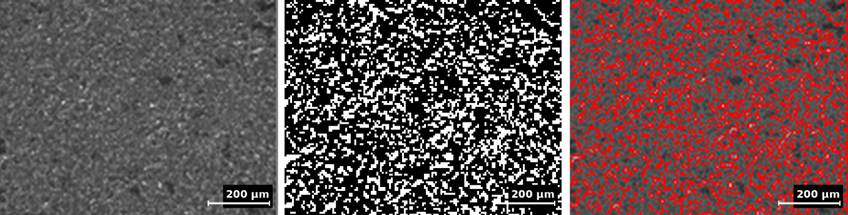
Fig. 16. Optical micrograph and ImageJ segmentation of the heat-affected zone for the E7016–E7016 electrode combination at 50× magnification; scale bar = 200 μm
|
Grayscale |
Threshold |
Overlay |
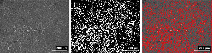
Fig. 17. Optical micrograph and ImageJ segmentation of the weld metal for the E7016–E7016 electrode combination at 50× magnification; scale bar = 200 μm
Table 3. Estimated ferrite and pearlite area fractions and microstructural characteristics of the BM, HAZ, and WM for different electrode combinations
|
Specimens |
Zone |
Estimated ferrite area fraction, mean ± SD (%) |
Estimated pearlite area fraction, mean ± SD (%) |
Morphology |
Microstructural characteristics |
|
6013–6013 |
BM |
71.87 ± 1.35 |
28.13 ± 1.35 |
Ferrite-dominant ferrite–pearlite structure |
The BM exhibited a ferrite-dominant matrix with dispersed pearlite regions and locally heterogeneous grain features. |
|
HAZ |
74.99 ± 0.22 |
25.01 ± 0.22 |
Fine partially transformed ferrite–pearlite structure |
The HAZ showed a relatively fine ferrite–pearlite distribution associated with the welding thermal cycle. |
|
|
WM |
73.87 ± 1.84 |
26.13 ± 1.84 |
Interlocking ferritic structure with locally directional features |
The WM exhibited a ferrite-dominant structure with dispersed pearlite and locally directional/interlocking features. |
|
|
6013–7016 |
BM |
70.83 ± 3.69 |
29.17 ± 3.69 |
Ferrite-dominant ferrite–pearlite structure |
The BM exhibited a ferrite-dominant matrix with dispersed pearlite regions and a relatively heterogeneous ferrite–pearlite appearance. |
|
HAZ |
71.68 ± 4.54 |
28.32 ± 4.54 |
Partially transformed ferrite–pearlite structure. |
The HAZ showed a transitional ferrite–pearlite microstructure with locally refined and heterogeneous features. |
|
|
WM |
68.88 ± 1.45 |
31.12 ± 1.45 |
Interlocking ferritic structure with locally directional features |
The WM exhibited dispersed pearlite within a ferritic matrix with locally directional/interlocking features. |
|
|
7016–6013 |
BM |
64.80 ± 2.47 |
35.20 ± 2.47 |
Ferrite-dominant ferrite–pearlite structure |
The BM contained a ferritic matrix with a comparatively higher estimated pearlite fraction. |
|
HAZ |
70.88 ± 2.59 |
29.12 ± 2.59 |
Partially transformed ferrite–pearlite structure. |
The HAZ exhibited a transitional ferrite–pearlite microstructure with locally refined and heterogeneous regions. |
|
|
WM |
72.08 ± 1.10 |
27.92 ± 1.10 |
Interlocking ferritic structure with locally directional features |
The WM showed a ferrite-dominant structure with dispersed pearlite and locally directional/interlocking features. |
|
|
7016–7016 |
BM |
72.66 ± 2.06 |
27.34 ± 2.06 |
Ferrite-dominant ferrite–pearlite structure |
The BM retained a relatively typical ferrite–pearlite matrix with dispersed pearlite regions. |
|
HAZ |
70.19 ± 0.93 |
29.81 ± 0.93 |
Partially transformed ferrite–pearlite structure. |
The HAZ showed a transitional ferrite–pearlite microstructure with relatively fine and locally heterogeneous features. |
|
|
WM |
76.14 ± 4.47 |
23.86 ± 4.47 |
Interlocking ferritic structure with locally directional features |
The WM exhibited the highest estimated ferrite fraction, with dispersed pearlite and locally directional/interlocking features. |
Note: Values are mean ± SD from three fields. Ferrite and pearlite fractions were estimated from light and dark regions using calibrated grayscale thresholding in ImageJ 1.54.
The phase estimation showed ferrite-dominant microstructures in all regions, with HAZ ferrite fractions of approximately 70–75%. The HAZ exhibited transitional and locally heterogeneous ferrite–pearlite features, reflecting the effect of the welding thermal cycle. The E6013–E7016 WM showed the lowest estimated ferrite fraction (68.88 ± 1.45%), whereas E7016–E7016 exhibited the highest value (76.14 ± 4.47%). These results indicate that the electrode sequence and welding thermal cycle modified the local ferrite–pearlite distribution, particularly in the HAZ and WM [3,4,28,29].
The estimated phase fractions should not be considered the sole determinants of mechanical behaviour. Ferrite generally favours ductility and toughness with comparatively lower hardness, whereas pearlite contributes more to strength and hardness. In the present joints, however, the highest WM ferrite fraction occurred in E7016–E7016, while E7016–E6013 exhibited the highest WM hardness and E6013–E6013 the highest UTS. Therefore, the observed mechanical response likely resulted from the combined effects of phase distribution, local morphology, weld-metal characteristics, thermal history, and microstructural heterogeneity.
The HAZ showed a transitional and locally heterogeneous ferrite–pearlite microstructure associated with the welding thermal cycle. Specific ferrite morphologies, such as polygonal, acicular, or Widmanstätten ferrite, were not differentiated because the present analysis was based on optical microscopy and semi-quantitative ImageJ segmentation. Therefore, the microstructure is conservatively described as ferrite-dominant ferrite–pearlite.
3.5 Corrosion behaviour
The corrosion behaviour of the BM and SMAW-welded specimens was evaluated by potentiodynamic polarization in 3.5 wt.% NaCl solution. Figure 18 presents the polarization curves obtained from the capping surfaces for the different electrode combinations.
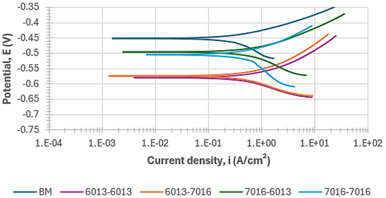
Fig. 18. Potentiodynamic polarization curves of the BM and SMAW-welded specimens measured on the capping surface in 3.5 wt.% NaCl solution
Table 4. Electrochemical corrosion parameters of SMAW-welded SS400 specimens in 3.5% NaCl solution
|
Specimen |
Ecorr (V) |
icorr (µA/cm²) |
Corrosion rate (mm/year) |
|
6013–6013 |
−0.580 |
0.8720 |
0.01010 |
|
6013–7016 |
−0.575 |
9.6328 |
0.11249 |
|
7016–6013 |
−0.497 |
9.4281 |
0.11004 |
|
7016–7016 |
−0.505 |
0.4700 |
0.00550 |
Figure 18 shows the potentiodynamic polarization curves, with the corresponding parameters summarized in Table 4. The 7016–7016 specimen exhibited the lowest icorr (0.4700 µA/cm²) and corrosion rate (0.00550 mm/year), followed by 6013–6013 (0.8720 µA/cm²; 0.01010 mm/year). The mixed-electrode joints showed higher corrosion rates, reaching 0.11004 mm/year for E7016–E6013 and 0.11249 mm/year for E6013–E7016. Although E7016–E6013 exhibited the most positive E<sub>corr</sub> (−0.497 V), its higher i<sub>corr</sub> indicates greater corrosion activity, consistent with the interpretation of polarization parameters reported in welded steels [30,17]. Variations in corrosion behaviour associated with welding conditions and electrode characteristics have also been reported for SMAW-welded steels [14,31]. Overall, the corrosion resistance followed the order E7016–E7016 > E6013–E6013 > E7016–E6013 > E6013–E7016.
3.6 Study limitations
This study was limited to 8 mm SS400 steel welded in the 1G position using four E6013/E7016 root–cap combinations under fixed parameters. Thermal cycles, cooling rates, grain size, impact toughness, and fracture characteristics were not evaluated. Specific ferrite morphologies, such as polygonal, acicular, and Widmanstätten ferrite, were not differentiated because the microstructural analysis was limited to optical microscopy and semi-quantitative ImageJ segmentation. Corrosion behaviour was assessed only by potentiodynamic polarization in 3.5 wt.% NaCl; therefore, the findings are limited to the investigated welding and testing conditions.
4 Conclusions
The E6013/E7016 deposition sequence influenced the tensile properties, distribution of hardness, microstructure, and corrosion behaviour of SMAW-welded SS400 steel. E6013–E6013 produced the highest welded-joint UTS of 464.37 ± 0.87 MPa and showed a relatively uniform ferrite–pearlite distribution, whereas E7016–E7016 achieved the highest YS of 331.47 ± 18.09 MPa. The highest weld-metal hardness was obtained with E7016–E6013, while E6013–E6013 exhibited the lowest and most uniform hardness profile. All investigated conditions exhibited ferrite-dominant microstructures, with E7016–E7016 showing the highest estimated WM ferrite fraction of 76.14 ± 4.47%. Corrosion resistance followed the order E7016–E7016 > E6013–E6013 > E7016–E6013 > E6013–E7016, with E7016–E7016 exhibiting the lowest corrosion rate of 0.00550 mm/year. Overall, no single electrode sequence provided the best response for all evaluated properties; however, E6013–E6013 offered a favourable balance of tensile strength, hardness uniformity, microstructural consistency, and relatively low corrosion rate, while E7016–E7016 provided the highest corrosion resistance under the investigated conditions.
Acknowledgements
The authors would like to express their gratitude to Diponegoro University for the academic support and facilities provided during this research. The authors also acknowledge the laboratory staff and technical personnel who assisted with specimen preparation and experimental testing.
References
- Baghel, P. K. (2022). Effect of SMAW process parameters on similar and dissimilar metal welds: An overview. Heliyon, 8(12), e12161. https://doi.org/10.1016/j.heliyon.2022.e12161
- Fitri, M., Hidayatullah, P., Wibowo, K. M., & Darmawan, A. S. (2021). The effect of SMAW welding currents on mechanical properties and microstructures of low carbon steels. Materials Science Forum, 1029, 15–23. https://doi.org/10.4028/www.scientific.net/MSF.1029.15
- Sumardiyanto, D., & Susilowati, S. E. (2019). Effect of welding parameters on mechanical properties of low carbon steel API 5L shielded metal arc welds. 9(1), 15–21. https://doi.org/10.5923/j.materials.20190901.03
- Chiong, R., Khandoker, N., Islam, S., & Tchan, E. (2019). Effect of SMAW parameters on microstructure and mechanical properties of AISI 1018 low carbon steel joints: An experimental approach. IOP Conference Series: Materials Science and Engineering, 495(1), 012093. https://doi.org/10.1088/1757-899X/495/1/012093
- Pratiwi, Y. R., & Wibowo, S. S. (2019). The effect of electrode and number of passes on hardness and microstructure of shielded metal arc welding. IOP Conference Series: Materials Science and Engineering, 515(1), 012072. https://doi.org/10.1088/1757-899X/515/1/012072
- Adiman, Budiarto, & Aprillius. (2020). The current strength welding analysis of electrode E6013 and E7016 type CS32 steel to the flows on microstructure and hardness. IOP Conference Series: Materials Science and Engineering, 725(1), 012002. https://doi.org/10.1088/1757-899X/725/1/012002
- Fernando, Y., Mulyadi, R., & Info, A. (2020). The effect on using different types of electrodes toward the tensile strength of the welding joints groove V low carbon steel type DIN. Teknomekanik, 3(2), 43–49. https://doi.org/10.24036/teknomekanik.v3i2.6072
- Susilowati, S. E., & Sumardiyanto, D. (2023). The effect of welding electrode variation on the mechanical properties and microstructure of API 5L shielded metal arc welds. Proceedings, 312–316. https://doi.org/10.5220/0011980500003582
- Junaidi, A., Saputra, D. A., Wilza, R., & Hendradinata, H. (2024). Analysis of variation E7016 electrode heating time and humidity on E7016 electrode tensile strength of joints welding material SS400. International Journal of Mechanics, Energy Engineering and Applied Science (IJMEAS), 2(3), 48–53. https://doi.org/10.53893/ijmeas.v2i3.305
- Aljufri, A., & Mawardi, I. (2022). Analysis of defects in SMAW welding joint using E 7016 electrode due to the direct cooling process. Journal of Welding Technology, 4(2), 48–54. https://doi.org/10.30811/jowt.v4i2.3304
- Kurniawan, A. N., & Widiastuti, I. (2018). The effect of variations in the shape of the seam on microstructure, hardness and tensile strength in the welding process of steel SS400 with the SMAW method. Journal of Mechanical Engineering and Vocational Education, 1(2), 75–80. https://doi.org/10.20961/jomeve.v1i2.27282
- Dewangan, S., Selvaraj, S. K., Karthikeyan, B., Adane, T. M., Chattopadhyaya, S., Królczyk, G., & Raju, R. (2022). Metallographic investigation on postweld heat-treated 0.21%C-1020 steel plates joined by SMAW method. Advances in Materials Science and Engineering, 2022, 1–11. https://doi.org/10.1155/2022/9377591
- Oktadinata, H., Pratomo, S. B., & Gumilar, A. (2021). Effect of nickel addition on the microstructure and toughness of shielded metal arc welded SS400 steel. Materials Science Forum, 1029, 41–46. https://doi.org/10.4028/www.scientific.net/MSF.1029.41
- Surojo, E., Wicaksana, N. I., Saputro, Y. C. N., Budiana, E. P., Muhayat, N., Triyono, & Prabowo, A. R. (2020). Effect of welding parameter on the corrosion rate of underwater wet welded SS400 low carbon steel. Applied Sciences, 10(17), 5843. https://doi.org/10.3390/app10175843
- Ramadhani, M., Rochiem, R., & Zain, M. I. (2023). Analysis of the effect of electrode variation and current on the welding results of Corten A steel using SMAW method on microstructure, corrosion resistance, and mechanical properties. Journal of Applied Sciences, 4(1), 10–20.
- Edberk, J. A. S., & Siva, N. (2020). Investigation of corrosion rate for different type of welding joints using shielded metal arc welding (SMAW). IOP Conference Series: Materials Science and Engineering, 834(1), 012055. https://doi.org/10.1088/1757-899X/834/1/012055
- Mohammed, R. G., & K, S. R. (2018). Studies on microstructure, mechanical and corrosion properties of high nitrogen stainless steel shielded metal arc welds. IOP Conference Series: Materials Science and Engineering, 330(1), 012044. https://doi.org/10.1088/1757-899X/330/1/012044
- Yuwono, I., Tranggono, A., Salim, A., Bisono, R. M., Pratama, D., Aditama, R., & Maulana, R. (2021). Characteristics of welding joint using SMAW weld method and result DT-NDT on low carbon steel materials. 6(4), 92–98.
- Efriandi, I. F. (2023). Analysis of penetrant test results of S355J2 steel welding connections for qualification welding. 4(1), 41–48.
- Kumar Vikash, Yadav Subodh Kumar, Vijetha, K., Mendhe, V., Kumari, A., Shrivastava, V., Goga, G., & J. A. (2025). An investigation of the effect of GMAW and SMAW processes on mechanical and microstructural properties of welded E350 grade steel. Scientific Reports, 15(1), 36338. https://doi.org/10.1038/s41598-025-20140-4
- American Welding Society. (2025). AWS D1.1/D1.1M:2025, Structural welding code—Steel. American Welding Society.
- British Standards Institution. (2009). BS EN 1011-1:2009, Welding—Recommendations for welding of metallic materials—Part 1: General guidance for arc welding. British Standards Institution.
- Wan, M., Sri, Y., Muhamad, N., & Muhammad, S. (2024). Porosity scale evaluation of shielded metal arc welding. JAMEA, 5(2), 1–6. https://doi.org/10.30880/jamea.2024.05.02.001
- Suleiman, H. O., & Young, J. (2021). Effect of welding groove and electrode variation to the tensile strength and macrostructure on 304 stainless steel and AISI 1045 dissimilar welding joint using SMAW process. Journal of Physics: Conference Series, 2117(1), 012018. https://doi.org/10.1088/1742-6596/2117/1/012018
- Mohd-lair, N. A., Yuyut, Y., Ahmad, Z., & Mohd, A. (2021). SMAW: The effects of currents and welding rod diameters on welded joint ultimate tensile strength using the full factorial DOE. Journal of Physics: Conference Series, 2129(1), 012071. https://doi.org/10.1088/1742-6596/2129/1/012071
- Arifin, A., Wijaya, M. R. Y. Q. A., Ode, L., Barata, A., & Ramli, M. I. (2024). The effect of preheating on the mechanical properties of AISI 1037 and AISI 304 welded joints using shielded metal arc welding. Materials, 17, 5780. https://doi.org/10.3390/ma17235780
- Gürkan, İ. (2022). Study of the microstructure and mechanical property relationships of shielded metal arc and TIG welded S235JR steel joints. Materials Science and Engineering: A, 830, 142320. https://doi.org/10.1016/j.msea.2021.142320
- Mannapovitch, S. R., Khamidovich, R. R., & Touileb, K. (2025). Effects of nanostructured functional ceramics additives coatings electrode on the structure and mechanical properties of SMAW welded joints. Crystals, 15, 260. https://doi.org/10.3390/cryst15030260
- Jiang, Z., Liang, D., & Zhou, T. (2018). Effects of welding on the change of microstructure and mechanical properties of low carbon steel. IOP Conference Series: Materials Science and Engineering, 523(1), 012065. https://doi.org/10.1088/1757-899X/523/1/012065
- Kumar, A., Shailesh, M., Rahul, M. P., Dariusz, C., & Chandan, F. (2024). Corrosion performance of super duplex stainless steel and pipeline steel dissimilar welded joints: A comprehensive investigation for marine structures. The International Journal of Advanced Manufacturing Technology, 1009–1033. https://doi.org/10.1007/s00170-024-14596-3
- Ashari, R., Eslami, A., Shamanian, M., & Asghari, S. (2019). Effect of weld heat input on corrosion of dissimilar welded pipeline steels under simulated coating disbondment protected by cathodic protection. Journal of Materials Research and Technology, 9(2), 2136–2145. https://doi.org/10.1016/j.jmrt.2019.12.044
Conflict of Interest Statement
The authors declare no conflict of interest.
Author Contributions
Data Availability Statement
All relevant data are included within the article.
Supplementary Materials
There are no supplementary materials to include.