Original Scientific Paper, Volume 23, Number 2, Year 2025, No 1276, pp 322-329
Received: Jan 11, 2025 Accepted: Apr 21, 2025 Published: Jun 16, 2025
DOI: 10.5937/jaes0-55948
INVESTIGATION OF THE WELDED LAYER HARDNESS AT RESTORATION OF ELECTRIC MOTOR SHAFTS
Abstract
The article is devoted to studying the influence of wire feed rate on the hardness of the welded layer during the restoration of electric motor shafts. The authors analyse the importance of optimal hardness to ensure the durability and reliability of the reconditioned parts. The paper considers various factors affecting the hardness of the welded layer, such as type of welding wire (AWS A5.18 ER70S-6, OK Tubrodur 35 G M, AWS A5.28 ER80S-G); cladding modes (feed rate, current, voltage); properties of the welded clad metal (fusion with the base, tendency to crack formation). Based on the conducted experiments, the optimal welding modes for each of the studied wires and the corresponding hardness values were determined. The obtained results allow us to conclude that the wire feed rate is one of the key parameters affecting the hardness of the welded layer.
Highlights
- The article investigates how wire feed rate affects the hardness of the welded layer when restoring electric motor shafts.
- Optimal welding modes and corresponding hardness values were determined for different welding wires based on experimental results.
- The wire feed rate is identified as a key parameter influencing the hardness of the welded layer.
- Cubic regression equations are presented as the best mathematical models to describe the relationship between welded layer hardness and wire feed rate for the studied materials.
Nomenclature
MAG - metal active gas;
ISO – international system organization;
KCV - impact strength;
А - relative elongation;
Re - yield strength;
Rm - tensile strength.
Keywords
Content
1 Introduction
Hardfacing of electric motor shafts is a common restoration method used when wear or damage to the shaft makes it unsuitable for further operation. This process allows to restore the geometry of the shaft, increases its wear resistance and corrosion resistance [1].
Shaft journals, bearing seats, and keyways are subjected to intensive wear during engine operation [2]. Hard facing allows to restoration of the original dimensions and geometry of these surfaces [3]. Scratches, risks, chips, and caverns can significantly reduce the strength of the shaft and lead to its destruction [4]. Hard facing can eliminate these defects. Corrosion of the shaft surface can lead to a reduction in its cross-section and strength [5]. Hard facing with a protective coating prevents further development of corrosion. Moreover, it is generally less expensive to restore a shaft by cladding than to replace a new shaft [6].
The optimum hardness of the clad layer is a key factor determining the durability and reliability of reconditioned motor shafts. Insufficient or excessive hardness of the welded layer can lead to premature wear, cracking, and peeling of the welded layer and consequently failure of the entire motor [7].
An overlay that is too soft will wear out quickly and cannot withstand the working loads [8]. A too hardening layer can lead to abrasive wear of the mating parts [9].
Insufficient hardness can lead to plastic deformation and failure of the layer under impact loads [10]. Excessive hardness makes the material brittle and increases the risk of cracking [11].
Improper hardness can impair the adhesion of the clad layer to the substrate, leading to delamination. Over-hardness can reduce fatigue resistance, which is especially critical for parts subjected to variable loads [12].
This will also not ensure the durability of the shaft in future operation.
The optimum hardness of the deposited layer is influenced by [13]:
- chemical composition and structure of the hardfacing material in relation to the base metal;
- methods of hardfacing (manual, automatic, submerged arc) and their technological modes.
2 Materials and methods
To obtain the required hardness of the deposited layer, the optimal cladding modes were selected: wire feed rate, current, voltage.
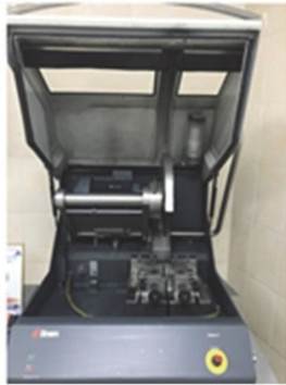
MAG welding machine Kemppi (Finland) was used for hard facing (Figure 1).
|
|
|

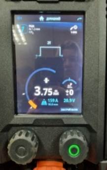
Fig. 1. Kemppi MAG welding machine.
The following wire grades c ⌀1.2 mm have been selected in order to take into account the best conditions for extending the life of the hardfaced shafts:
1. AWS A5.18 ER70S-6 (ISO 2560:2018);
2. OK Tubrodur 35 G M;
3. AWS A5.28 ER80S-G (ISO 2560:2018).
Table 1 shows the chemical compositions of the wires.
Table 1. Chemical composition and physical and mechanical properties of hard facing materials
|
Wire material |
С, % |
Si, % |
Mn, % |
P, % |
S, % |
Cr, % |
Ni, % |
Re, МPa |
Rm, МPa |
А, % |
KCV, J/cm2 |
|
AWS A5.18 ER70S-6 |
0.06-0.15 |
0.8-1.15 |
1.4-1.85 |
0.025 |
0.035 |
0.15 |
0.15 |
420 |
500 |
20 |
42 |
|
OK Tubrodur 35 G M |
0.20 |
1.0 |
1.4 |
0.030 |
0.035 |
1.50 |
- |
497 |
588 |
26 |
58 |
|
AWS A5.28 ER80S-G |
0.07-0.15 |
0.7-1.2 |
1.2-1.8 |
0.025 |
0.035 |
0.2-0.6 |
0.15 |
440 |
530 |
20 |
42 |
The selected materials have the necessary characteristics for obtaining a high-quality welded layer with the specified properties.
For the hardfacing experiment, three flat specimens made of Grade Fe 360B steel (ISO 630:2012) with a thickness of 10 mm were prepared.
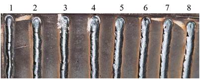
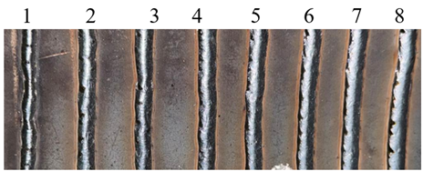
On each of the specimens, eight welded layers from the above wires were made (Figure 2).
The samples were welded in a CO2 (100%) protective gas environment.
 а) |
|
 c) |
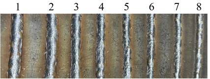
Fig.2. Deposited samples; a) AWS A5.18 ER70S-6 wire; b) OK Tubrodur 35 G M wire; c) AWS A5.28 ER80S-G wire; wire feed speed: 1 - 2.0 m/min; 2 - 2.25 m/min, 3 - 2.5 m/min, 4 - 2.75 m/min, 5 - 3.0 m/min, 6 - 3.25 m/min, 7 - 3.5 m/min, 8 - 3.75 m/min
Figure 3 shows the equipment for sample preparation and hardness research. The research was carried out in the testing laboratory of the engineering profile “Integrated Development of Mineral Resources” (IIP “KORMA”) of Abylkas Saginov Karaganda Technical University.
The samples with cladding for further analysis were cut across the harfacing direction. An automatic cutting machine UNIT OM-2 equipped with water cooling of the cut zone was used to cut the samples (Figure 3a).
The process of preparation of micro cuts of the investigated samples is carried out in accordance with the standard technique [14].
|
|
|
|
 а
а b)
b)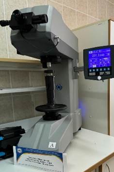 c)
c)Fig. 3. Equipment for specimen preparation and hardness testing; a) UNITOM-2 automatic benchtop cutting machine; b) LABOPOL-5 automatic sample grinding and polishing machine; c) Wilson VH1150 hardness tester
The cut samples were ground and polished using an automatic machine LABOPOL-5 (Figure 3b).
The resulting hardness of the clad was measured using a Wilson VH1150 hardness tester (Figure 3c).
The ground specimens and the pattern of hardness measurement in the specimen are shown in Figure 4.
|
|
|
|
|

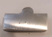
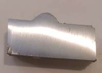
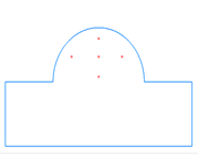
Fig. 4. Welded specimen slides and hardness measurement scheme of the hardfasing; a) AWS A5.18 ER70S-6 wire; b) OK Tubrodur 35 G M wire; c) AWS A5.28 ER80S-G; d) hardness measurement points of the hardfacing
The main technological parameter regulated in the hardfacing process was the wire feed speed. Voltage and welding current were set automatically on a Kemppi MIG welding machine.
The main requirement for the welded seam was to obtain the greatest depth of penetration of the welded layer while ensuring the fusion of the welded metal with the test specimen [15]. Technological modes of cladding are given in Table 2. The number of experiments was chosen as minimal and sufficient for planning the experiment n = 23 [16].
Table 2. Technological modes of hardfacing with different wires
|
Experiment No. |
AWS A5.18 ER70S-6 |
OK Tubrodur 35 G M |
AWS A5.28 ER80S-G |
||||||
|
V, m/min |
I, A |
U, V |
V, m/min |
I, A |
U, V |
V, m/min |
I, A |
U, V |
|
|
1 |
2.0 |
100 |
19.1 |
2.0 |
100 |
20.0 |
2.0 |
100 |
18.8 |
|
2 |
2.25 |
109 |
20.1 |
2.25 |
105 |
20.0 |
2.25 |
105 |
19.5 |
|
3 |
2.5 |
119 |
20.5 |
2.5 |
98 |
19.5 |
2.5 |
98 |
20.0 |
|
4 |
2.75 |
128 |
20.4 |
2.75 |
96 |
19.2 |
2.75 |
96 |
19.5 |
|
5 |
3.0 |
136 |
20.4 |
3.0 |
93 |
19.5 |
3.0 |
94 |
19.6 |
|
6 |
3.25 |
144 |
20.4 |
3.25 |
150 |
20.5 |
3.25 |
150 |
20.2 |
|
7 |
3.5 |
151 |
20.6 |
3.5 |
149 |
20.0 |
3.,5 |
149 |
20.0 |
|
8 |
3.75 |
159 |
20.9 |
3.75 |
100 |
20.5 |
3.75 |
100 |
20.9 |
3 Results and discussion
Based on the experiments performed, the hardness values for each welding wire were established (Table 3).
Table 3. Results of HV hardness measurements
|
Experiment No. |
AWS A5.18 ER70S-6 |
OK Tubrodur 35 G M |
AWS A5.28 ER80S-G |
|
1 |
269.3 |
324.5 |
188.0 |
|
2 |
286.6 |
338.7 |
189.9 |
|
3 |
290.4 |
396.0 |
192.5 |
|
4 |
335.0 |
396.3 |
208.8 |
|
5 |
335.7 |
398.0 |
243.3 |
|
6 |
344.3 |
422.0 |
246.6 |
|
7 |
368.0 |
440.0 |
269.7 |
|
8 |
371.5 |
453.5 |
274.0 |
The values of the obtained thermostats meet the normative requirements [17], however, the optimal modes taking into account the quality of the welded seam are: 4 mode - for AWS A5.18 ER70S-6; 5 mode - for OK Tubrodur 35 GM; 8 mode – AWS A5.28 ER80S-G.
Minitab program was used to establish the regression dependence between the influence of technological parameters of cladding on the hardness of the clad (Figure 5).
According to the Pareto diagram, it can be concluded that the wire feed speed and voltage are significant factors affecting the hardness.
For a more complete analysis of the experimental data, residual diagrams were constructed (Figure 6).
The graphs of the figure confirm the presence of linear regression and correlation of the residuals of the samples.
Mathematical models allow us to find optimal solutions for various problems [18, 19], including the selection of different hardacing materials with different modes.
|
|
|
|
|
а) |
b) |
с) |
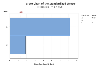
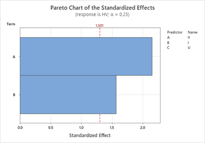
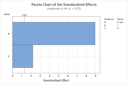
Fig. 5. Pareto diagram of the standardized effect; а) AWS A5.18 ER70S-6; b) OK Tubrodur 35 G M; с) AWS A5.28 ER80S-G
|
|
|
|
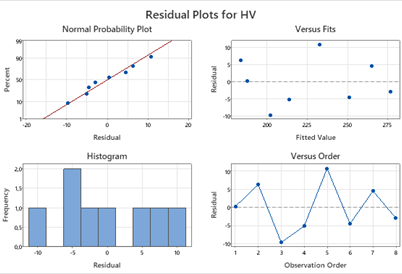
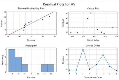

Fig. 6. Residual diagrams of regression analysis; с) AWS A5.28 ER80S-G
Since the main technological parameter affecting the hardness of the welded layer (Y) is the wire feed rate (X) in correlation with the other two (current and voltage), a mathematical model for this relationship can be developed.
In order to obtain an optimal mathematical model describing the effect of wire feed rate on the hardness of the welded layer, several different equations were obtained for different hardfacing materials (Table 4, 5, 6).
Table 4. Regression dependences of AWS A5.18 ER70S-6 wire hardness on feed rate
|
№ |
Regression type |
Regression equation |
Correlation coefficient |
Coefficient of determination |
Average approximation error, % |
|
1 |
linear |
y=57.0381x+62.6155 |
0.9688 |
0.9385 |
3.3071 % |
|
2 |
quadratic |
y=11.0286x2−6.3762x+150.1548 |
0.9733 |
0.9473 |
3.0203 % |
|
3 |
cubic |
y=−45.1232x3+400.2165x2− 1099.2045x+1147.4487 |
0.9898 |
0.9797 |
1.6657 % |
|
4 |
logarithmic |
y=63.9138+157.1135lnx |
0.9548 |
0.9116 |
3.9432 % |
|
5 |
hyperbolic |
y=376.9124- 414.4424/x |
0.9314 |
0.8676 |
4.8954 % |
Table 5. Regression dependences of OK Tubrodur 35 G M wire hardness on feed rate
|
№ |
Regression type |
Regression equation |
Correlation coefficient |
Coefficient of determination |
Average approximation error, % |
|
1 |
linear |
y=70.9143x+192.2464 |
0.9602 |
0.9220 |
2.3553 % |
|
2 |
quadratic |
y=−19.1238x2+180.8762x+40.4512 |
0.9689 |
0.9387 |
1.9626 % |
|
3 |
cubic |
y=33.8424x3−311.0147x2 +1000.4974x−707.5193 |
0.9749 |
0.9503 |
1.8765 % |
|
4 |
logarithmic |
y=189.0365+199.9948lnx |
0.9689 |
0.9388 |
1.9230 % |
|
5 |
hyperbolic |
y=592.5971- 541.714/x |
0.9706 |
0.9421 |
2.0131 % |
Table 6. Regression dependences of AWS A5.28 ER80S-G wire hardness on feed rate
|
№ |
Regression type |
Regression equation |
Correlation coefficient |
Coefficient of determination |
Average approximation error, % |
|
1 |
linear |
y=61.1810x+149.2048 |
0.9733 |
0.9473 |
1.9217 % |
|
2 |
quadratic |
y=−11.1810 |
0.9773 |
0.9552 |
1.7513 % |
|
3 |
cubic |
y=−11.4747x3+87.7887x2 −152.4326x+314.0658 |
0.9783 |
0.9570 |
1.6610 % |
|
4 |
logarithmic |
y=147.3982+171.6147lnx |
0.9768 |
0.9542 |
1.7601 % |
|
5 |
hyperbolic |
y=492.5400- 461.6666/x |
0.9718 |
0.9445 |
2.1777 % |
Analyzing the regression equations of Tables 4 - 6, we can conclude that cubic regressions describe the relationship between the hardness of the welded layer and the wire feed rate in the best way with a smaller approximation error:
- y = −45.1232x3+ 400.2165x2– 1099.2045x + 1147.4487 – for AWS A5.18 ER70S-6;
- y = 33.8424x3– 311.0147x2+ 1000.4974x – 707.5193 – for OK Tubrodur 35 G M;
- y = −11.4747x3 + 87.7887x2 − 152.4326x – for AWS A5.28 ER80S-G.
4 Conclusions
1. Taking into account the requirements to the hardness of electric motor shafts, as well as the greatest depth of penetration layer (2.54 mm) while ensuring the fusion of the clad metal with the base, the following optimal modes are determined:
- AWS A5.18 ER70S-6 - (V = 2.75 m/min; I = 128 A; U = 20.4 V);
- OK Tubrodur 35 G M - (V = 3.0 m/min; I = 93 A; U = 19.5 V);
- AWS A5.28 ER80S-G - (V = 3.75 m/min; I = 100 A; U = 20.9 V).
2. Optimal hardness for cladding wires taking into account technological modes are: AWS A5.18 ER70S-6 - 335 ÷ 340 HV; OK Tubrodur 35 G M - 398 ÷ 400 HV; AWS A5.28 ER80S-G - 270 ÷ 275 HV;
3. As a result of the calculation, regression equations determining the dependence of hardness of the welded layer on the wire feed rate were obtained during the planning of the experiment;
4. Optimization of electric motor shaft hardfacing processes with the help of properly selected materials and technological modes brings several significant advantages to machine-building enterprises:
- properly selected surfacing materials allow for increased hardness, and wear resistance, which makes it more durable;
- high-quality shaft restoration allows for significantly extending their service life and postponing the need to replace them with new ones, which reduces repair costs.
Acknowledgements
The research was conducted using the authors’ personal financial resources.
References
- Pradeep, G. R. C., Ramesh, A., & Durga, P. B. (2010). A review paper on hardfacing processes and materials. International Journal of Engineering Science and Technology, 2(11), 6507–6510.
- Nurzhanova, O., Zhukova, A., & Bučinskas, V. (2023). Investigation of the performance properties of parts surfaces to be recovered by semiautomatic hardfacing. Trudy Universiteta, (2), 52–58. https://doi.org/10.52209/1609-1825_2023_2_52
- Klimpel, A. (2020). Industrial surfacing and hardfacing technology, fundamentals and applications. Welding Technology Review, 91(12), 33–42. https://doi.org/10.26628/wtr.v91i12.1094
- Zharkevich, O., Taimanova, G., & Mukhitova, A. (2023). Analysis of shaft defects of electric motors and methods of their restoration. Trudy Universiteta, (4), 3–9. https://doi.org/10.52209/1609-1825_2023_4_3
- Olugbade, T. O., Ojo, O. T., Omiyale, B. O., Olutomilola, E. O., & Olorunfemi, B. J. (2021). A review on the corrosion fatigue strength of surface-modified stainless steels. Journal of the Brazilian Society of Mechanical Sciences and Engineering, 43, 421. https://doi.org/10.1007/s40430-021-03148-5
- Nurzhanova, O., Zharkevich, O., Bessonov, A., Naboko, Y., Abdugaliyeva, G., Taimanova, G., & Nikonova, T. (2023). Simulation of the distribution of temperature, stresses and deformations during splined shafts hardfacing. Journal of Applied Engineering Science, 21(3), 837–845.
- Kikai, N., Ronbunshu, G., & Hen, A. (2007). Destruction phenomenon about the spline shaft. Transactions of the Japan Society of Mechanical Engineers, Part A, 73(725), 80–87. https://doi.org/10.1299/kikaia.73.80
- Kenchi, R. K. M. (2012). The effects of welding processes on microstructure and abrasive wear resistance for hardfacing deposits. Bonfring International Journal of Industrial Engineering and Management Science, 2(2), 28–34. https://doi.org/10.9756/BIJIEMS.1298
- Garbade, R., & Dhokey, N. (2021). Overview on hardfacing processes, materials and applications. IOP Conference Series: Materials Science and Engineering, 1017, 012033. https://doi.org/10.1088/1757-899X/1017/1/012033
- Nashid, H., Ferguson, W. G., Clifton, G. C., Hodgson, M., Battley, M., Seal, C., & Choi, J. H. (2014). Non-destructive method to investigate the hardness–plastic strain relationship in cyclically deformed structural steel elements. Bulletin of the New Zealand Society for Earthquake Engineering, 47(3), 181–189.
- Joseph, P., Babu, M. N., & Albert, S. K. (2024). Fracture behavior of hardfacing alloy coated over stainless steel under quasi-static and dynamic loads. Journal of Materials Engineering and Performance, 33(23), 13019–13029. https://doi.org/10.1007/s11665-024-10389-7
- Zhang, Y., Sang, X. T., Xu, G., & Wang, G. (2023). Fatigue crack propagation of the gradient surface-modified layer of high-strength steel. International Journal of Fatigue, 177, 107921. https://doi.org/10.1016/j.ijfatigue.2023.107921
- Zharkevich, O., Nurzhanova, O., Zhunuspekov, D., Naboko, Y., Buzauova, T., Abdugaliyeva, G., Mateshov, A., & Bessonov, A. (2023). Determination of optimal hardfacing modes for recovering electric motor shafts. Tehnički Vjesnik, 30(3), 951–957. https://doi.org/10.17559/TV-20220719104215
- International Organization for Standardization. (2019). ISO 643:2019. Micrographic determination of the apparent grain size.
- Zharkevich, O. M., Nurzhanova, O., Bessonov, A., Naboko, Y., Abdugaliyeva, G., Taimanova, G., & Nikonova, T. (2023). Simulation of the distribution of temperature, stresses and deformations during splined shafts hard facing. Journal of Applied Engineering Science, 21(3), 837–845. https://doi.org/10.5937/jaes0-42774
- Mussayev, M., Sherov, K., Kassymbabina, D., Abdugaliyeva, G., Donenbayev, B., Kardassinov, S., Karsakova, N., & Tussupova, S. (2024). Research of wear and increasing wear resistance of the working part of busbar punching tools by surfacing method. Journal of Applied Engineering Science, 22(3), 654–664. https://doi.org/10.5937/jaes0-51175
- GOST 12080–66. (1966). Kontsy valov tsilindricheskiye.
- Zhetesova, G., Zharkevich, O., Pleshakova, Y., Platonova, Y., Yurchenko, V., & Buzauova, T. (2017). Building mathematical model for gas-thermal process of coating evaporation. Metalurgija, 55(1), 63–66.
- Bezkorovainyy, P. G., Teliman, I. V., Malybaev, N. S., & Shestakov, V. S. (2023). Hydraulic excavator bucket modeling with a straight shovel along a defined trajectory. Material and Mechanical Engineering Technology, 1(1), 29–33. https://doi.org/10.52209/2706-977X_2023_1_29
Conflict of Interest Statement
The authors declare no conflicts of interest.
Author Contributions
Data Availability Statement
All data supporting the findings of this study are included within the article.
Supplementary Materials
No supplementary materials were used; all relevant information is presented in the article.