Volume 24 article 1328 pages: 213-226
Received: Jul 11, 2025 Accepted: Mar 17, 2026 Available Online: May 30, 2026 Published: May 31, 2026
DOI: 10.5937/jaes0-60077
MECHANICAL DAMAGE ASSESSMENT IN CONCRETE BEAMS REINFORCED WITH STEEL AND POLYPROPYLENE FIBERS USING ULTRASONIC PULSE VELOCITY TESTING
Abstract
Concrete beams are structural elements primarily subjected to vertical loads, including self-weight (dead load) and externally applied actions (live load). The sustained interaction of these loads induces bending deformations. As with all structural materials, concrete beams experience mechanical damage when the applied stresses exceed their ultimate capacity, typically manifested through cracking, which occurs on the tensile face opposite the load application. For several decades, fiber reinforcement has been employed worldwide to enhance the physical and mechanical properties of concrete, particularly its residual strength and crack control. In this study, concrete specimens were reinforced with two types of fibers—steel and polypropylene—and evaluated using ultrasonic pulse velocity (UPV) testing to characterize mechanical damage. After curing time, UPV measurements were taken to assess internal damage development under flexural loading. Based on the experimental data, predictive equations are proposed to estimate mechanical damage as a function of pulse velocity, allowing for improved evaluation of reinforced concrete behavior under stress.
Highlights
- Ultrasonic pulse velocity was used to assess mechanical damage in fiber-reinforced concrete beams.
- Steel and polypropylene fibers improved crack control and residual structural integrity.
- UPV measurements showed strong correlation with damage levels during flexural loading.
- The method enables non-destructive evaluation of fiber-reinforced concrete structures.
Keywords
Content
1 Introduction
Concrete is the most widely used material in modern infrastructure, and its proper application requires thorough analysis of its structural behavior, particularly in response to load-induced deformations. The use of fibers in composite materials predates the invention of modern cement, as early civilizations incorporated elements such as animal hair, straw, and plant fibers into adobes to improve tensile strength and reduce cracking, as noted by Antillon [1].
Currently, steel and polypropylene fibers are incorporated into concrete mixes to enhance toughness and provide better crack control. Deformation analysis allows the calculation of internal stresses, where strain levels under static or dynamic loading are directly related to the system's stiffness and, consequently, its modulus of elasticity [2]. Upon concrete failure, the toughness index is typically recorded, while post-failure data are often disregarded. However, when fibers are used as reinforcement, their distribution within the concrete matrix enables post-failure load transfer, increasing flexural capacity and reducing crack propagation [3].
Naaman [4] highlights that for fiber–matrix reinforcement to be effective, the fibers must exhibit properties such as adequate bonding strength (comparable to the tensile strength of the matrix), a higher elastic modulus than concrete, greater tensile strength, and preferably ductile behavior when combined with a brittle cementitious matrix.
Polypropylene fibers exhibit hydrophobic behavior, which enhances their resistance to moisture within the cementitious matrix. According to Kakooei et al. [5], the hydrophobic nature of polypropylene does not significantly affect the water demand in the concrete mix. Steel fibers typically enhance shear and torsional strength and promote a more uniform distribution of cracks within the concrete matrix [6]. The appearance of cracks in a beam is typically associated with flexural deformation, indicating the presence of internal structural damage.
Table 1. Characteristics of different fibers [6]
|
Fiber type |
Specific weight |
Tensile strength |
Young's modulus |
Failure elongation |
|
(g/cm3) |
(MPa) |
(GPa) |
(%) |
|
|
Steel |
7,84 |
345-3000 |
200 |
4-8 |
|
Glass |
2,5 |
1000-2600 |
70-80 |
1,5-3,5 |
|
Polypropylene |
0,9-0,95 |
200-760 |
3.5-15 |
5-25 |
|
Polyester |
1,4 |
400-600 |
8.3 |
9-13 |
|
Concrete (For comparison) |
2,4 |
2-6 |
20-50 |
- |
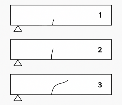
Fig. 1. Flexural crack progression [7]
According to Ospina et al. [8], the initial crack in a beam typically develops on the tensile face, opposite the point of load application. The crack propagates vertically toward the neutral axis in response to the applied flexural stress; this type of damage is visibly evident and can be detected without specialized instrumentation.
Mechanical damage quantification in concrete was studied by Lemaitre [9], who proposed a relationship between the uniaxial stress at fracture ($\sigma_u$) and the material's ultimate stress ($\tilde{\sigma}_u$), expressed through the damage parameter $D_c$, defined by the equation:
If the value of Dc is between 0,5 and 0,9, it indicates the presence of damage.
Additionally, Lemaitre proposed an expression to estimate mechanical damage (Dc) based on the relative reduction in wave velocity, calculated using the equation:
Where $\tilde{V}_L$ is the wave velocity in the damaged material and VL is the wave propagation velocity in the undamaged material. When a value between 0,5 and 1 is obtained, it indicates that there is already significant damage, because mechanical damage in beams is closely linked to their flexural behavior, it is essential to conduct standardized flexural strength tests to quantify this response. This type of test allows for variation in the load application rate, facilitating the collection of data on stress distribution and failure progression within the specimen, as outlined in NTC 2871 [10], which aligns with ASTM C78/C78M.
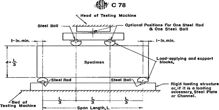
Fig. 2. Schematic view of the apparatus is suitable for the determination of the flexural strength of concrete by using a third-point loading. Source: ASTM C78
The calculation of stress in concrete is given by the expression:
Where R is the Stress (MPa), P is the applied load indicated by the testing machine (N), L is the distance between supports (mm), b is the average width of the specimen (mm) and d is the average height of the specimen (mm).
Concrete strength can also be assessed through non-destructive testing (NDT); although these methods do not yield exact values, they provide highly reliable approximations. A major advantage of NDT is its low cost, as it does not require specimen destruction and allows repeated measurements on the same element.
Among NDT techniques, the ultrasonic pulse velocity (UPV) test is considered one of the most effective for evaluating mechanical damage in concrete, as it is based on the principle that the velocity of compressive waves propagating through concrete is directly related to its elastic properties [11, 12]. When properly applied, this method yields reliable information on the internal condition of the concrete.
However, caution must be exercised during in-situ applications, as the range of pulse velocities associated with concrete quality is relatively narrow (typically 3,5–4,8 km/s). Guidelines for this method are provided in the Colombian standard NTC 4325 [13], which corresponds to ASTM C597 — Standard Test Method for Pulse Velocity Through Concrete.
The UPV method consists of measuring the travel time of an ultrasonic pulse between a transmitting transducer (Tx) and a receiving transducer (Rx) placed on opposite faces of the concrete element.
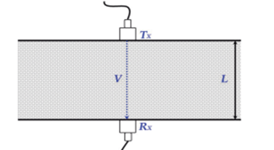
Fig. 3. UPV test scheme. Source: Vidaud-Quintana, E. [14]
Wave propagation velocity depends on the elastic modulus and density of the material and can therefore be used to evaluate the material’s elastic behavior. In an idealized infinite, homogeneous, elastic, and isotropic medium, the compressive wave velocity V, is determined by the Equation:
Where E is the elastic modulus (kN/mm2), : $\rho$ is the material density (kg/m3), and $\mu$ is the Poisson's ratio.
The velocity of the ultrasonic pulse is associated with the properties of the concrete and its density; therefore, it allows predicting the quality state of the concrete in hardened state, which is expressed in meters per second (m/s), which is determined by the simplified relation, V=L/t, where V is the transmission velocity, L is the separation between the transducers, and t is the transit time [13, 14] Although the UPV procedure is relatively simple, obtaining reliable results requires strict attention to testing conditions. Proper acoustic coupling between the transducer and the concrete surface is essential. This is typically achieved using coupling agents such as petroleum jelly, liquid soap, or thick grease. If the concrete surface is excessively rough or irregular, it must be prepared—either by grinding or applying a thin layer of plaster or quick-setting mortar—to ensure optimal contact with the transducers, as described by León et al. [15]. Determining the flexural strength of the concrete is necessary in order to correlate it with the information from the UPV test.
Despite the extensive use of ultrasonic pulse velocity (UPV) testing to assess concrete quality and detect internal defects, most existing studies focus on static evaluations of undamaged or pre-cracked concrete elements. Limited research has investigated the continuous evolution of ultrasonic pulse velocity in concrete elements subjected to progressive mechanical loading, particularly in fiber-reinforced systems where the presence of fibers alters crack development and post-failure behavior. Furthermore, few studies have attempted to quantitatively relate UPV measurements with mechanical damage parameters, such as those proposed in Lemaitre’s damage mechanics framework, during active flexural loading. Establishing such relationships is important for improving the interpretation of non-destructive measurements and for enabling the use of UPV as a practical tool for structural assessment, damage evaluation, and potential in-situ monitoring of concrete elements. Therefore, this study aims to experimentally investigate the relationship between ultrasonic pulse velocity and the mechanical damage developing in micro-reinforced concrete beams subjected to flexural loading, combining destructive flexural testing with comparative UPV measurements in order to derive predictive relationships between wave velocity reduction and the damage parameter .
2 Materials and methods
This study was conducted at the Concrete Laboratory of the Faculty of Engineering, Universidad Militar Nueva Granada, Cajicá (Colombia) for concrete mixing and curing, and at the Calle 100 campus in Bogotá for destructive (flexural) and non-destructive (UPV) testing.
A quantitative approach was adopted based on the use of destructive and non-destructive testing methods. A total of 42 beams were fabricated with different reinforcement configurations, comprising six beams per variable under analysis. Each beam had a span of 0,5 m and a square cross-section of 0,15 m × 0,15 m. The mechanical properties of the steel and polypropylene fibers used are summarized in Table 2.
Table 2. Technical specifications of the fibers used. Source: Manufacturer datasheets [16]
|
Fiber type |
Technical properties |
||
|
Steel fibers (SUPERCAM FR 80) |
Length (mm) |
Diameter (mm) |
Average tensile strength (MPa) |
|
60 |
0,75 |
760 |
|
|
Polypropylene fibers (SikaFiber AD) |
Elongation at break (%) |
Elastic modulus (Gpa) |
Tensile strength (MPa) |
|
20 – 30 |
14,7 |
290 – 340 |
|
The fiber dosage was defined based on the recommendations provided by the respective manufacturers. For polypropylene fibers, a dosage of 1 kg/m3 is recommended, while for steel fibers, a dosage ranging from 20 to 40 kg/m3 is suggested. The concrete mix criteria and material dosage quantities were based on the methodology reported by Ospina et al. [8], which follows the parameters established by the American Concrete Institute (ACI 211.1-91) for concrete proportioning [17].
Table 3. Criteria chosen for concrete mix design. Source: Ospina, Lizarazo and Salas [8].
|
Parameter |
Value |
|
Design compressive strength |
28 MPa |
|
Modulus of rupture (flexural strength) |
4,23 Mpa |
|
Slump (consistency) |
8 in o 200 mm aprox. |
|
Cement density |
2,91 g/cm3 |
|
Maximum aggregate size |
11/2 in o 38,1 mm |
|
Nominal maximum aggregate size |
1 in o 25,4 mm |
|
Bulk density of coarse aggregate |
1589 kg/m3 |
|
Bulk density of fine aggregate |
1574 kg/m3 |
|
Specific gravity of coarse aggregate |
2540 kg/m3 |
|
Specific gravity of fine aggregate |
2510 kg/m3 |
|
Fineness modulus (fine aggregate) |
3,1 |
A total of six reinforced concrete mixtures were evaluated, three mixtures incorporated polypropylene fibers at contents of 1,0%, 1,5%, and 2,0% relative to the cement weight; for these percentages were selected to investigate the influence of increasing polypropylene fiber content on the mechanical behavior of the concrete while maintaining workability during mixing, since excessive amounts of polypropylene fibers can significantly reduce mix homogeneity [18]. For comparison purposes with the steel fiber mixtures, whose dosage is typically expressed in kg/m3, the equivalent polypropylene fiber contents were estimated using a reference fiber density of 910 kg/m³, resulting in approximate values of 9, 13,5, and 18 kg/m3. It should be noted that these values correspond only to an equivalent conversion for comparison between fiber types and do not represent the original mixture design parameter.
Three additional mixtures incorporated steel fibers at dosages of 25, 50, and 75 kg/m3. These dosages were selected because higher fiber content increases the concrete’s mechanical resistance but also adds significant dead weight to the structure [19], so the resulting data will be used to compare which type of fiber provides effective reinforcement without negatively affecting the structural load. The experimental program therefore allows comparison between polypropylene and steel fibers in terms of their contribution to concrete reinforcement and structural performance.
After curing, plain (unreinforced) concrete specimens were tested to obtain baseline values for comparison with the results from steel and polypropylene fiber-reinforced mixes. For destructive testing, an MTS Landmark 370 system with a monotonic loading configuration was used to apply the load until failure, this setup allowed measurement of the maximum load sustained by each beam. For the non-destructive test, a Proceq Pundit 200 touchscreen device
was used to measure ultrasonic pulse velocity (UPV) within the concrete; this dual setup enabled simultaneous monitoring of UPV variation during flexural loading, allowing correlation between ultrasonic response and applied mechanical stress.
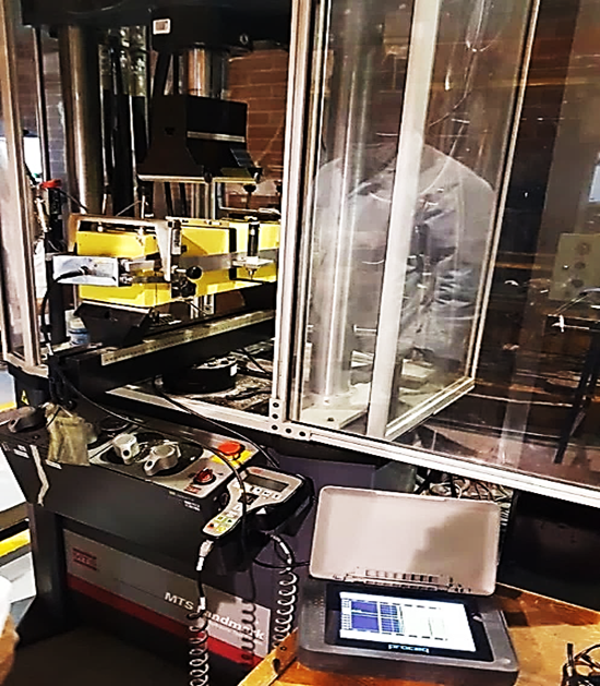
Fig. 4. Destructive test setup (flexural failure with monotonic load setup) and non-destructive test (UPV)
To ensure proper instrument setup, custom clamping fixtures were designed for both the UPV specimens and the LDT transducers, as shown in Figure 5. This configuration allowed the UPV test to be conducted simultaneously with flexural loading in the MTS system, and optimized the contact pressure between the specimen, coupling agent, and beam, thus enabling more accurate measurements, as proper contact between the specimen and transducer is crucial for ensuring consistent and reliable data.
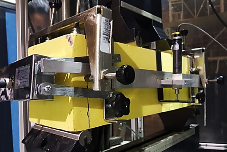
Fig. 5. Beam clamping device, for LDT transducers and VPU transducers. Source: Authors.
Once failure occurred in the specimens, unlike in plain concrete beams, the presence of reinforcing fibers allowed the load to continue being applied, enabling observation of the post-cracking behavior and the additional strength provided by the fibers.
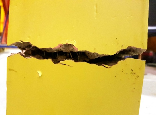
Fig. 6. Crack in concrete beam reinforced with steel fibers 50 kg/m3. Source: Authors.
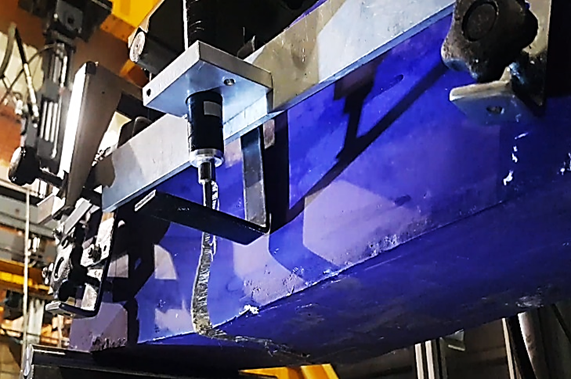
Fig. 7. Crack in concrete beam reinforced with 2.5% polypropylene fibers. Source: Authors.
3 Results and discussion
According to current design codes such as the ACI 318 and Colombia’s NSR-10, synthetic fibers—such as polypropylene—are permitted as complementary reinforcement, particularly for crack control and post-cracking behavior enhancement, but not as a replacement for structural steel reinforcement. In this study, the polypropylene fibers were not used as primary reinforcement, but rather as an additive to improve ductility and delay sudden failure, especially at a dosage of 1,5%, which demonstrated the best overall performance. Therefore, the experimental design remains within the framework of code-compliant applications for fiber-reinforced concrete.
After conducting the tests on the various beams with their respective reinforcement configurations, the resulting data were compiled for analysis, graphical representation, equation development, and conclusion formulation. The ultrasonic pulse velocity (UPV) was higher in plain concrete beams due to lower internal porosity in the absence of fibers, which facilitated more efficient wave propagation. However, flexural strength increased with higher steel fiber content, while it showed an inverse relationship with increasing amounts of polypropylene fibers.
Table 4. Maximum ultrasonic pulse velocity on single beams. Source: Authors.
|
Beam |
Maximum pulse elocity (m/s) |
|
1 |
3331 |
|
2 |
3018 |
|
3 |
2919 |
|
4 |
3187 |
|
Average |
3114 |
|
Standard deviation |
182,41 |
The ultrasonic pulse velocity (UPV) values obtained for the plain concrete beams are summarized in Table 4, where the maximum velocity for each beam was recorded, the average was calculated, and the standard deviation was determined. Based on these values, the average and standard deviation were plotted in order to compare variability and identify the most representative value for this type of beam.
As shown in Figure 8, specimens 1 and 3 fall outside the range defined by the standard deviation. Since specimens 2 and 4 fall within the defined range, they were compared with respect to the calculated average, with specimen 4 showing the closest value, and therefore selected as the reference for comparison with the reinforced beams. The same procedure was applied to each reinforcement type and dosage.
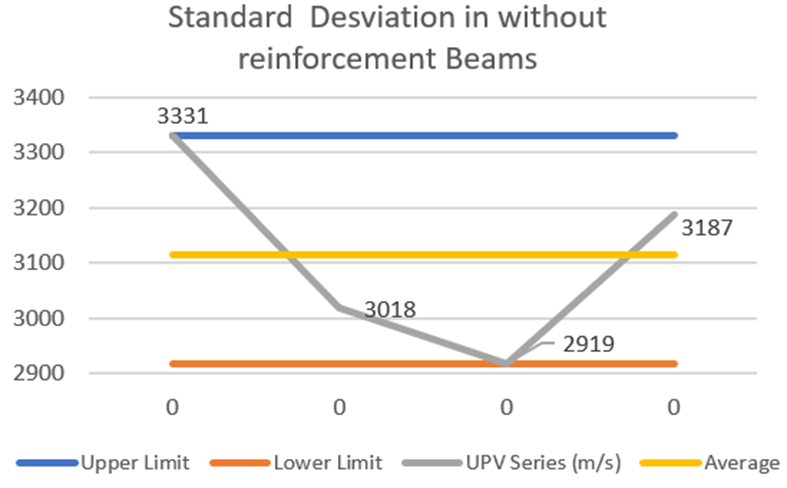
Fig. 8. Standard eviation in without reinforcement beams. Source: Authors.
Table 5 presents the average UPV values and corresponding standard deviations for each reinforcement type and dosage across all tested beams. Given the two different reinforcement types and three dosage levels for each, each mix type was analyzed to determine which configuration performs best in terms of flexural strength and mechanical damage.
Table 5. Average measurements on without reinforcement beams and beams with reinforcement. Source: Authors.
|
Reinforcement |
Average maximum bending stress (MPa) |
Standard deviation flexural strength |
Average maximum ultrasonic pulse rate (m/s) |
Standard velocity maximum ulse velocity |
|
Without reinforcement |
3,4 |
0,24 |
3114 |
182,41 |
|
SRFC 25 kg/m3 |
3,52 |
0,08 |
3105 |
57,32 |
|
SRFC 50 kg/m3 |
3,31 |
0,26 |
2275 |
108,66 |
|
SRFC 75 kg/m3 |
4,16 |
0,1 |
3095 |
21,43 |
|
PFRC 1% |
3,62 |
0,33 |
3084 |
25,59 |
|
PFRC 1,5% |
3,42 |
0,15 |
2851 |
127,63 |
|
PFRC 2% |
2,1 |
0,08 |
2127 |
98,56 |
After selecting the representative data for each reinforcement dosage, the bending stress diagram was constructed (Figure 9), where similar values were observed for beams reinforced with 25 kg/m3 and 75 kg/m3 of steel fibers, as well as with 1.5% polypropylene fibers. The 50 kg/m3 steel fiber mix and the 1 % polypropylene fiber mix exhibited higher flexural strength.
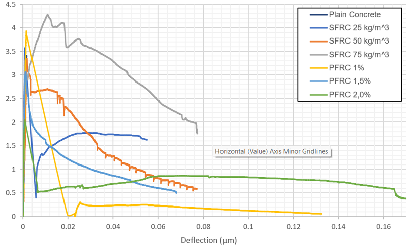
Fig. 9. Bending stress in reinforced concrete beams. Source: Authors.
Figure 10 presents the mechanical damage graph, which was developed by combining the results of the flexural strength and UPV tests, since the continuous application of load until failure, particularly in reinforced beams, allowed additional post-failure UPV readings to assess concrete conditions under sustained loading. As shown in the graph, steel reinforcements at all three dosages (25, 50, and 75 kg/m3) and the 1,5% polypropylene reinforcement contributed to extending the structural response beyond initial failure, since the mechanical damage exceeded the theoretical threshold (0,5 – 1) [9], indicating significant cracking without leading to sudden collapse, as observed in plain concrete beams.
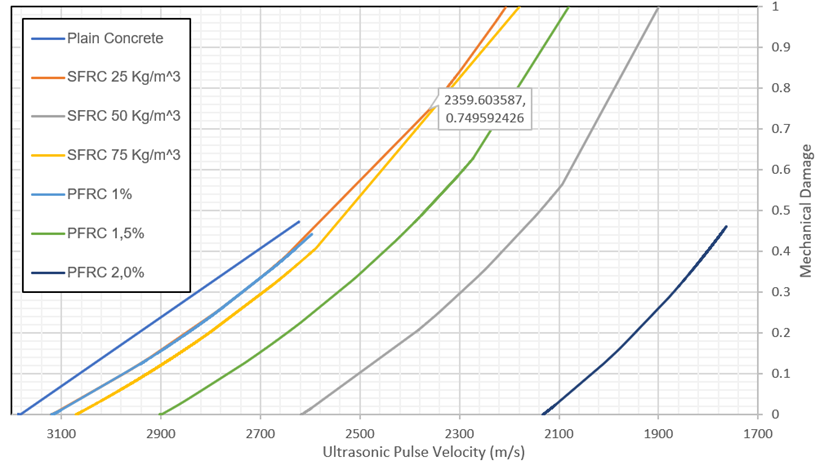
Fig. 10. VPU vs. Mechanical damage in reinforced concrete beams. Source: Authors.
Figure 11 shows that the flexural behavior of beams reinforced with steel fibers was very similar across all dosages, with similar trends in flexural strength and deformation (creep), attributed to the use of the same concrete matrix. However, plasticity increased with higher fiber dosages, leading to the construction of the mechanical damage curve (Figure 12) to help identify the optimal fiber dosage. This graph revealed similar performance for the 75 kg/m3 and 25 kg/m3 steel fiber dosages; however, the 75 kg/m3 dosage provided higher flexural strength compared to the other configurations. The 25 kg/m3 dosage improved the concrete’s behavior by forming an internal fiber network that helped prevent collapse at the onset of cracking, providing additional post-cracking resistance.
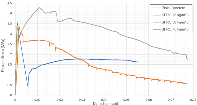
Fig. 11. Bending stress in steel fiber reinforced concrete beams. Source: Authors.
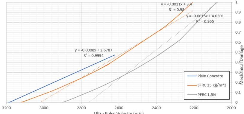
Fig. 12. UPV vs. Mechanical damage in steel fiber reinforced concrete beams. Source: Authors.
As shown in Figure 13, the performance of mixes with polypropylene fibers was highly variable, and the different polypropylene dosages did not exhibit the consistent behavior observed with steel fiber reinforcement. Higher polypropylene dosages resulted in lower flexural strength and reduced mechanical damage resistance, indicating that the 2,0% mix may not be suitable for structural concrete reinforcement. Among the remaining two mixes, the 1% dosage exhibited good flexural strength but relatively low resistance to mechanical damage, whereas the 1,5% dosage demonstrated superior performance in both flexural strength and mechanical damage resistance.
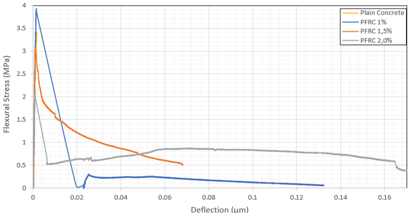
Fig. 13. Bending stress in polypropylene fiber reinforced concrete beams. Source: Authors.
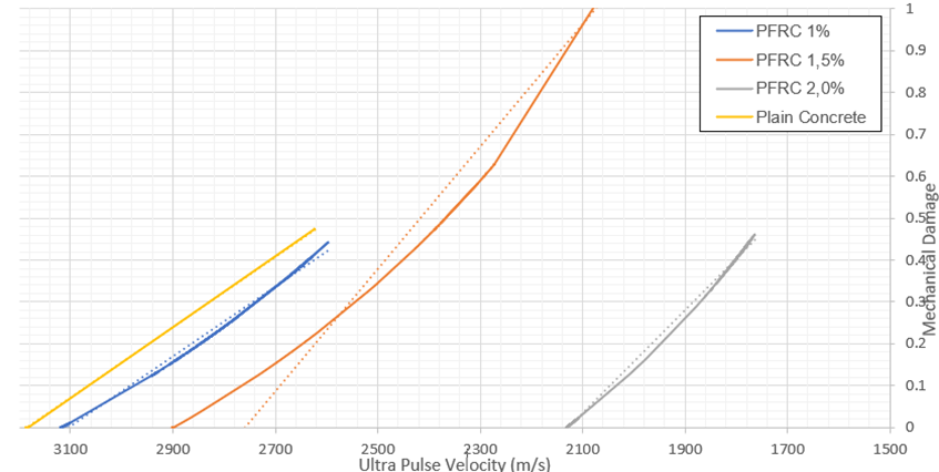
Fig. 14. Comparison of reinforcement results with polypropylene fibers. Source: Authors.
As Lemaitre, severe mechanical damage occurs when the damage index exceeds a value of 0.5, which corresponds to a material that has lost more than 50% of its effective load-bearing capacity and can no longer be considered structurally reliable. This is confirmed in Figures 10 and 15, where the plain concrete beam experienced a sudden collapse when the damage index approached 0,5, interrupting UPV data acquisition due to the absence of a continuous medium for wave propagation through the specimen. In contrast, fiber-reinforced beams allowed continued wave propagation due to crack bridging, resulting in measurable UPV values and corresponding damage indices above 0,5. To generate the UPV (m/s) vs. mechanical damage graph, Equation (3) was used, taking the maximum UPV value as a reference and relating it to the other UPV readings obtained during the test. Once the damage index was calculated throughout the MTS test, the corresponding graph was plotted.
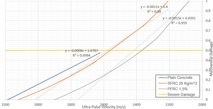
Fig. 15. Comparison of results for beams reinforced with: SFRC 25 kg/m3, PFRC 1,5% and without reinforcement. Source: Authors.
Beams reinforced with 25 kg/m³ of steel fibers and 2% of polypropylene fibers exhibited sufficient internal cohesion to produce comparable performance. Although both reinforcements reduced the wave propagation velocity compared to plain concrete beams, they improved damage resistance by providing post-cracking capacity, which extends the structural response time and offers a margin for corrective action. Another advantage is that the element does not collapse immediately upon exceeding its elastic limit but instead transitions from a rigid to a ductile behavior, as illustrated in the mechanical behavior graphs.
Based on these findings, a series of regression analyses were performed to derive an equation that models the relationship between mechanical damage and UPV, as presented in Table 6.
Table 6. Equations obtained. Source: Authors.
|
Type of reinforcement |
Type of linear equation |
Coefficient of determination |
|
Plain Concrete |
Dc = -0,0008V + 2,6787 |
R2 = 0,9994 |
|
PFRC 9 kg/m3 |
Dc = -0,0008V + 2,5420 |
R2 = 0,9944 |
|
PFRC 13,5 kg/m3 |
Dc = -0,0015V + 4,1729 |
R2 = 0,9654 |
|
PFRC 18 kg/m3 |
Dc = -0,0012V + 2,6271 |
R2 = 0,9989 |
|
SFRC 25 kg/m3 |
Dc = -0,0012V + 3,4844 |
R2 = 0,9848 |
|
SFRC 50 kg/m3 |
Dc = -0,0014V + 3,5434 |
R2 = 0,9319 |
|
SFRC 75 kg/m3 |
Dc = -0,0011V + 3,4277 |
R2 = 0,9760 |
|
Dc = Mechanical damage |
||
|
V = Ultrasonic pulse velocity (m/s) |
||
For verifying whether the proposed equations can accurately predict the mechanical damage in fiber-reinforced concrete beams, the bending stress and UPV data were correlated to produce the corresponding validation graph (Figure 16), where at least nine coordinate points were identified and substituted into the regression equations to calculate the corresponding mechanical damage values, which were then compared with the experimental results.
As shown in Figure 10, the damage index (Dc) for the plain concrete beam reached values up to 0,5, confirming Lemaitre's theoretical threshold [9], indicating the need to consider the corresponding lower limit of UPV when using the regression equation for this type of beam. Using the Solver tool in Excel, the minimum pulse velocity corresponding to Dc = 0,5 was calculated as 2723,4 m/s.
For the plain concrete beam, the regression equation used is:
- Dc = -0,0008V + 2,6787
Using a UPV of 2750 m/s as an example:
- Dc = -0,0008(2750) + 2,6787
- Dc = -2,2 +2,6787
- Dc = 0,48
A comparison using the same velocity across the other regression equations yields the damage values shown in Table 7.
Table 7. Mechanical damage values using equations obtained from the following equations. Source: Authors.
|
V = 2750 |
|
|
Reinforcement |
Dc |
|
Without reinforcement |
0,4787 |
|
PFRC 1% |
0,342 |
|
PFRC 1,5% |
0,0479 |
|
PFRC 2% |
-0,6729 |
|
SFRC 25 kg/m3 |
0,1844 |
|
SFRC 50 kg/m3 |
-0,3066 |
|
SFRC 75 kg/m3 |
0,4027 |
The negative values observed in Table 7 indicate that the selected pulse velocity exceeds the upper applicability limit of the regression equations, as mechanical damage values (Dc) must always be greater than zero. Therefore, it was necessary to establish valid input limits for each evaluated regression equation, as presented in Table 8.
In addition, fiber-reinforced beams, the minimum valid pulse velocity corresponds to a damage index of Dc = 1, representing the point at which the element can no longer sustain any additional load. Based on the parameters obtained in Table 8, the theoretical curves were compared with the experimental data, as shown in Figure 16.
Table 8. Pulse rate limits for the obtained equations. Source: Authors.
|
Reinforcement type |
Regression equation |
Valid UPV range (m/s) |
|
Plain concrete |
Dc = -0,0008V + 2,6787 R² = 0,9994 |
Vmax= 3348,38 m/s Vmin= 2723,38 m/s |
|
PFRC 1% |
Dc = -0,0008V + 2,542 R² = 0,9944 |
Vmax=3177,5 m/s Vmin= 2098,38 m/s |
|
PFRC 1,5% |
Dc = -0,0015V + 4,1729 R² = 0,9654 |
Vmax= 2781,93 m/s Vmin= 2115,27 m/s |
|
PFRC 2% |
Dc = -0,0012V + 2,6271 R² = 0,9989 |
Vmax=2189,25 m/s Vmin= 1355,92 m/s |
|
SFRC 25 kg/m3 |
Dc = -0,0012V + 3,4844 R² = 0,9848 |
Vmax=2903,67 m/s Vmin= 2070,33 m/s |
|
SFRC 50 kg/m3 |
Dc = -0,0014V + 3,5434 R² = 0,9319 |
Vmax=2531 m/s Vmin= 1816,71 m/s |
|
SFRC 75 kg/m3 |
Dc = -0,0011V + 3,4277 R² = 0,976 |
Vmax=3116,09 m/s Vmin= 2207 m/s |
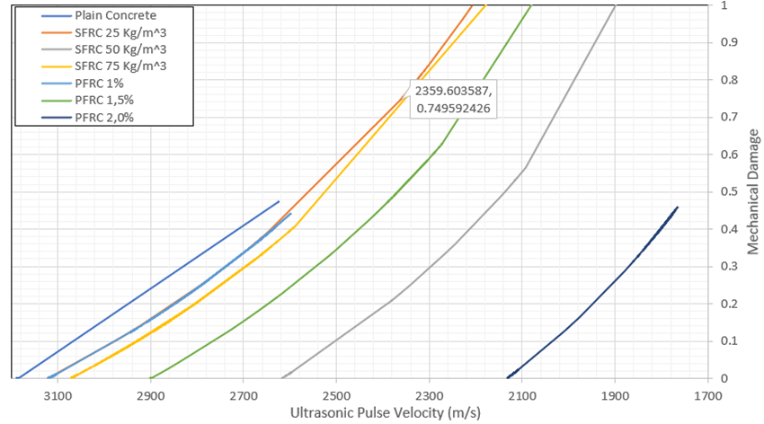
Fig. 16. Comparison of experimental values and predictive equations. Source: Authors.
The relationships established between ultrasonic pulse velocity (UPV) and the mechanical damage parameter provide a practical framework for the non-destructive assessment of concrete structures. Since the propagation velocity of ultrasonic waves is directly related to the internal condition of the material, the correlations obtained in this study allow the estimation of mechanical damage levels in concrete beams subjected to flexural loading.
Also, from an engineering perspective, these relationships may contribute to structural assessment procedures by enabling the detection and quantification of damage without requiring destructive testing. In addition, the proposed correlations may support condition monitoring strategies, where periodic UPV measurements could be used to evaluate the evolution of structural damage over time. This approach could be particularly useful for in-situ inspection of reinforced concrete structures, where non-destructive techniques provide valuable information for maintenance planning, safety evaluation, and service-life management.
4 Conclusions
The behavior of plain concrete is often unpredictable. However, reinforcing it enhances its mechanical stability, making cracking more observable and enabling better prediction of failure.
Among the reinforcements studied, steel fibers demonstrated the best mechanical performance in terms of improving concrete strength. Nonetheless, increasing the fiber content complicates the mixing process and increases the beam's dead weight. An analysis of the SFRC mixes indicates that higher fiber content results in greater flexural strength. Furthermore, the presence of steel fibers prevents abrupt structural failure, as they act as an internal support mesh that allows the beam to sustain higher levels of mechanical damage under loading. This confirms the findings discussed in the state of the art.
Ultrasonic pulse velocity (UPV) was highest in plain concrete beams due to lower internal porosity in the absence of reinforcement, which facilitates better wave propagation. In SFRC beams, the 25 kg/m3 and 75 kg/m3 mixes exhibited similar wave propagation, with UPV values only 2% and 3.5% lower, respectively, than those of plain concrete. However, the 50 kg/m3 mix showed a 17% reduction in UPV, likely due to poor fiber distribution, which increased internal porosity.
Although the 75 kg/m3 steel fiber mix achieved the highest flexural strength, the 25 kg/m3 mix exhibited comparable performance in terms of mechanical damage. Therefore, the 25 kg/m3 dosage was preferred, as it required less material and involved a simpler mixing process. In contrast, polypropylene fibers reduce the overall weight of the beam, but higher dosages increase internal porosity, which leads to reduced flexural strength and earlier structural failure.
In PFRC mixes, flexural strength was inversely proportional to fiber dosage, while the damage index increased proportionally. This is attributed to the fibers limited ability to bridge cracks, making the beam behave similarly to plain concrete under load. As polypropylene dosage increased, UPV decreased—similar to what was observed in the SFRC 50 kg/m3 mix—due to greater difficulty in achieving a homogeneous mix, which in turn increased porosity and reduced concrete quality.
Although the PFRC 2% mix showed lower flexural strength than the 1 % mix, it demonstrated superior resistance to mechanical damage and helped avoid sudden failure. For this reason, it is recommended as the most appropriate polypropylene dosage among those tested.
The regression equations developed in this study provide an approximation of the mechanical damage index of concrete based on ultrasonic pulse velocity. The variations observed across mixes and dosages align with the theoretical thresholds proposed by Lemaitre, particularly in the range where the damage index is below 0,5 (indicating no imminent failure) and above 0,5 (indicating that existing cracks may compromise structural safety under further stress).
Finally, the proposed regression equations provide a useful correlation between ultrasonic pulse velocity (UPV) and the mechanical damage parameter, their applicability is limited to the experimental conditions considered in this study. The relationships were derived from tests conducted on concrete beams with a compressive strength of approximately 28 MPa, a specific beam geometry, under controlled laboratory conditions. Therefore, the use of these equations for concrete elements with different material properties, structural configurations, or loading conditions should be approached with caution. Further studies are required to validate the proposed correlations for other concrete strengths, structural elements, and long-term loading scenarios.
Acknowledgements
Authors thanks to the Universidad Militar Nueva Granada for allowing the use of its concrete laboratory for carrying out the tests. In the case of the authors Miguel Ángel Ospina García, Julián Carrillo León, Saieth Baudilio Chaves Pabón and Yohana Catalina Parra Gómez, it is mentioned that this scientific document is the result of their academic work as professors at the Universidad Militar Nueva Granada. Additionally, the authors give credit to the Universidad Militar Nueva Granada for the support received in the development of this research and in the production of this scientific document.
References
- Antillón, J. (2016). Uso de fibras en el concreto. Construcción y Tecnología en Concreto, 5(7), 28–29.
- Meza de Luna, A., et al. (2014). Experimental mechanical characterization of steel and polypropylene fiber reinforced concrete. Revista Tecnológica de la Facultad de Ingeniería de la Universidad del Zulia, 37(2), 106–115.
- Najimi, M., Farahani, F. M., & Pourkhorshidi, A. R. (2009). Effects of polypropylene fibers on physical and mechanical properties of concretes. https://www.irbnet.de/daten/iconda/CIB13842.pdf
- Naaman, A. E. (2000). Fibre reinforcements for concrete: Looking back, looking ahead. In Fifth International RILEM Symposium on Fibre-Reinforced Concrete (FRC) (pp. 65–86).
- Kakooei, S., Akil, H. M., Jamshidi, M., & Rouhi, J. (2012). The effects of polypropylene fibers on the properties of reinforced concrete structures. Construction and Building Materials, 27(1), 73–77.
- Mármol Salazar, P. C. (2010). Hormigones con fibras de acero: Características mecánicas.
- Toirac Corral, J. (2004). Patología de la construcción: Grietas y fisuras en obras de hormigón; origen y prevención. Ciencia y Sociedad, 29(1), 72–114.
- Ospina García, M. Á., Lizarazo, J. M., & Salas Montoya, A. (2020). Evolución del daño mecánico del concreto SFRC sometido a flexión mediante el análisis de la velocidad del pulso ultrasónico. INGE CUC, 16(1).
- Lemaitre, J. (2009). Mechanics of solid materials. Cambridge University Press.
- ICONTEC. (2004). Norma técnica colombiana NTC 2871: Método de ensayo para determinar la resistencia del concreto a la flexión. Bogotá D.C.
- Aguirre Quispe, L. E. (2015). Resistencia a la compresión del concreto a partir de la velocidad de pulsos de ultrasonido. Revista Civilízate, (6), 18–20.
- Crowe, G. V. (2009). Introduction to non-destructive testing (2nd ed.). The American Society for Nondestructive Testing. https://source.asnt.org/1pekds3
- ICONTEC. (1997). Norma técnica colombiana NTC 4325: Método de ensayo para la determinación de la velocidad del pulso ultrasónico a través del concreto. Bogotá D.C.
- Vialud Quintana, E., & Vialud Quintana, I. (2016). Ultrasonido: Aplicación para la determinación del módulo de elasticidad dinámico. Revista Construcción y Tecnología en Concreto, 5(8), 32–35. https://www.studocu.com/ec/document/universidad-central-del-ecuador/ensayo-de-materiales-/-ultrasonido-informeacion/84900136
- León Ramírez, J. A. (2014). Evaluación del proceso de daño y deterioro mecánico del concreto reforzado con fibras mediante técnicas acústicas (Tesis de maestría). Universidad Nacional de Colombia. https://repositorio.unal.edu.co/handle/unal/51994
- SIKA. (2012). Sikafiber FE-530/35 GH. https://apliarqui.com/wp-content/uploads/2016/05/Manual-Productos-Sika-2015.pdf
- American Concrete Institute. (2009). Standard practice for selecting proportions for normal, heavyweight and mass concrete (ACI 211.1).
- Muñoz Cebrián, F. (2011). Comportamiento mecánico del hormigón reforzado con fibra de polipropileno multifilamento: Influencia del porcentaje de fibra adicionado (Tesis de grado). Universidad Politécnica de Valencia. https://riunet.upv.es/handle/10251/13552
- Ortiz Barbosa, S. L. (2015). Determinación de la influencia de la fibra de acero en el esfuerzo a flexión del concreto para una f’c = 280 kg/cm² (Tesis de grado). Universidad Nacional de Cajamarca. http://hdl.handle.net/20.500.14074/636
Conflict of Interest Statement
The authors declare that there is no conflict of interest regarding the publication of this paper.
Author Contributions
Data Availability Statement
The data that support the findings of this study are available from the corresponding author upon reasonable request.
Supplementary Materials
No supplementary materials are associated with this article.