Volume 24 article 1335 pages: 328-334
Received: Dec 04, 2025 Accepted: Apr 22, 2026 Available Online: May 23, 2026 Published: May 31, 2026
DOI: 10.5937/jaes0-63218
MODIFICATION OF SIZE EFFECT FORMULA FOR CONCRETE BEAMS WITHOUT SHEAR REINFORCEMENT
Abstract
The current state of engineering science and practice has been concluded that the size effect cannot be overlooked, especially in the calculation of the shear capacity. Models based entirely on fracture mechanics have led to complex formulations inconvenient for practical use. Models based on simple theories, are resulting in a formula for determining the shear capacity of reinforced concrete. They are practically convenient, but multiple empirical parameters without a clear physical meaning are involved in their formulation. In the present study one modification of a size effect formula is presented. The purpose of this modification is to replace an empirical coefficient with a fracture mechanic’s parameter with a clear physical meaning.
Highlights
- In the Bazant and Yu’s size effect model, the parameter $d_o$ can be replaced by the Hillerborg characteristic length. Thus, the modification of the size effect formula proposed in the present sudy, was arrived at.
- Physically, Hillerborg Characteristic length is directly related to the size of the fracture process zone and is a conventional way to measure fracture capacity of a structure even in a shear loads.
- The present results show that including such parameters gives good enough results and it is conventional to include them in the size effect formulas.
Keywords
Content
1 Introduction
Modelling reinforced concrete beams depending on their size is a serious problem, solved by many authors all over the world, such as Bajant, Kazemi [1], Zararis, Papadakis [2] and Bajant, Planas [3]. Many theoretical models have been developed for concrete and reinforced concrete and their tensile behaviour. Based on classical fracture mechanics, a solution can be carried out with the classical two-parameter models of Karihalo and Shah – [4, 5] or the three-parameter model of Hillerborg [6], which require a nonlinear solution. As a result, the solution gives both the bearing capacity and the entire crack propagation process. These models do not consider the presence of shear stresses at critical diagonal crack propagation, which is a problem. There are models that consider this relationship in some form, but as a result the solutions become significantly more complex [7]. In all these models, the effect of size is implicitly included in the full solution for crack propagation.
In the literature, there are another type of simplified models that aim to be more convenient for practice. These models focus on determining the load-carrying capacity of the cross section considering the size effect.
The models of concrete behaviour could be classified into three different classes. One of them in general could be named: "Full Behaviour Models" as Hillerborg’s model, An, Maekawa and Okamura’s, Xu and Needleman’s, etc. [6, 8, 9]. The second type could be named "Carrying Capacity Models" as Karihaloo and Barenblatt’s model, Jenq and Shah’s, crack sliding model, etc. [4, 5, 10] and the third one "Size Effect Formulas" – Bažant and Yu’s model, Bentz and Collins’s, Zararis и Papadakisq’s etc. [11, 12, 13, 2]. In fact, the name of the last class of models has been already distinguished in world literature.
The last class of models focuses entirely on the study of the size effect, considering as many factors as possible. They are based on simple theories and lead to a single formula for determining the shear capacity. The main purpose of these models is their direct implementation in codes and the use in practice. For this reason, the number of these models is the largest, which has led to an already recognizable name.
The initial models of this class were based almost entirely on experimental data. This leads to empirical formulas that are inconvenient to use and lead to misunderstanding on the part of designers. Due to the use of experimental results obtained for beams with small (sizes) dimensions and the subsequent extrapolation of the data, the results for real beams finally do not have the required accuracy.
This leads to a more in-depth study of the influence of individual parameters involved in the size effect. This has been done by Bazant and Yu in [11, 12]. Other models of this class are that of Benz and Collins, described in [13], Zararis and Papadakis [2] and the model of Kazemi and Brujerdian - see [14]. As a further development of this type of models, size effect formulation is adapted and applicated from Dönmez and Bažant to the punching shear in slabs in [15]. In other studies, the authors propose a formulation for some concrete without coarse aggregate [16] or for lightly reinforced concrete (see [16]). Cunbao and alt. present an investigation of the size effect and proposes a formula for anisotropic geomaterials [18], based on a Bazant size effect law. In their study Ashour and Kara propose a simplified, empirical expression for the shear capacity of FRP reinforced concrete beams – see [19].
A common feature of these models is the use of relatively simple theories to derive a formula for the bearing capacity of shear beams. Another common feature is the presence of empirical parameters included in the formula. The main reason for this is the impossibility of theoretically determining a large part of the parameters influencing the size effect.
2 Materials and methods
In the present study a model of “size effect formulae” is used to perform calculations of the load-carrying capacity of shear beams. One of these models is the well-known model of Bazant and Yu [11, 12], which will be briefly presented.
2.1 Bazant and Yu’s size effect formula
To develop their model Bazant and Yu [11, 12] analyse the influence of the different parameters such as steel ratio, shear span, cross section size, and the aggregate particles size over the shear capacity. Next, they use the potential energy theorem to develop the shape of the size effect formula. In their model, they take as a main parameter the compressive strength of the concrete. The formulation of $d_o$ appears, as transitional characteristic size, is based on the functional dimensional analysis [11]. In their further study [12], they they perform a statistical analysis of experimental data in dependence on the sizes of the beams and calibrate this parameter by experimental results see [12]. Finally, they propose size effect formula in the following variant:
where $nu_c$ is the shear strength, $\rho$ is the reinforcement ratio $\rho = \frac{A_s}{b \cdot d}$, $b$ is the cross section width, $A_s$ is the reinforcement area, $d$ is the distance from the top of the cross section to the centroid of the longitudinal reinforcement, $a$ is the shear span, $f_c'$ is the compressive strength of the concrete, $\mu$ is the empirical coefficient $\mu = 13.3$ for the Imperial units), $d_o$ is, according their final formulation, an empirical coefficient depending on aggregate size and can be calculated by compressive strength. It has a dimension of length and varies from $100 \text{ to } 600 \, \text{mm}$ ($4 \text{ to } 24 \, \text{in}$).
where $\kappa = 3.8 \sqrt{d_a}$ if $d_a$ is known,$\kappa = 3.330$ (for the Imperial units) if not.
The ultimate load according to the Bazant and Yu model is calculated by:
where $V_u$ is the ultimate shear force in the shear span.
One should notice that in this model they exclude the reinforcement cover and work with the effective cross section. Bazant and Yu’s model is simple to use and considers almost all parameters influencing size effect in shear.
2.2 Modification of the size effect formulae
The size effect law in its earliest formulations [3] postulate the idea of proportionality between a general parameter $d_o$ and fracture process zone. Furthermore, Planas and Elices propose a size effect formula for small size beams on bending where instead of $d_o$ they use the proportion $\frac{l_{ch}}{\mu_0}$ and value of $\mu_0 = 8.64$. In other size effect model a proportion of $\frac{\pi}{8}$ is used – see [3]. The idea of using solely fundamental material and geometric properties is presented also in the work of Nelson and alt. [17] where a size effect model for lightly reinforced concrete beams on bending is proposed. In this work the authors propose a ’generalised’ characteristic length $D_o$ which is calculated on the base of mode I stress intensity factor $K_I$.
To develop presented in the previous section model, Bazant and Yu are made a separate analysis for small and for large beam size [11]. For large size of beam, by using Hillerborg characteristic length, they develop the large size asymptote. As a next step they develop the transitional connection between the two types of structure (small and large) and define $d_o$ as a parameter depending on geometry of the structure and is proportional to the characteristic length. After calibration with experimental data, they present the law in its final form (1) including parameter $d_o$ in the form (2) [12]. Main idea of representing $d_o$ as a parameter depending on the aggregate size and an empirical constant is to simplify size effect law and to obtain an engineering formula. At the same time, they move this parameter away from its original essence and in parallel with this $d_o$ becomes more difficult for calculation of reason of absence of information for the aggregate size.
In present study the idea of turning back to the initial formulation of the parameter $d_o$ is proposed. In (3) the parameter $d_o$ of the Bazant and Yu’s model has a dimension of length, but in its final form is without a clear physical meaning embedded in it, and its determination is carried out with an empirical formula. On the other hand, the Hillerborg’s characteristic length is a material constant is determined based on other material constants is as follows [6]:
where$l_ch$ is defined as the characteristic length and has the dimension of length, $E$ is the modulus of elasticity, $G_f$ represents the fracture energy, and $f_t$ is the tensile strength of the concrete.
Physically, this quantity is directly related to the size of the fracture process zone. Taking into account the idea of proportionality between$d_o$ and $l_ch$ in the initial stage of the definition here a proportional factor equals one is proposed, or:
This leads to a modification of Bazant and Yu's model, which achieves using fracture mechanics parameters and reduction of empirical dependencies. The ultimate load is calculated by using (3).
2.3 Analysis of proposed modification
From theoretical point of view the aggregate size included in (3) and the strength characteristic, $f_c'$ leads to an indirect relation with the fracture process zone. In the other hand, the characteristic length is directly connected with the process zone and includes fracture characteristic which could be considered as an advantage of the present modification. Bazant and Yu in their work make a profonde analysis of all parameters of the model by calibrating them with large number of experiments. During the studies for the present work, it was found as theoretical as numerical correspondences between $d_o$ and $l_ch$. From many performed comparisons between the two parameters, part of which are presented in the next section, the practical applicability of proposed corelation was confirmed. Even though, for to establish it’s the correctness further investigation and calculations are needed.
An analysis of the formulation (2) and (4) shows that a determination of shear strength by using (2) means considering mostly the compressive strength of the concrete as a physical parameter and indirectly the other physical parameters influenced by the aggregate size (if this value is known). But the replacing (2) by (4) into (1) leads to considering the influence of other important material parameters over the shear strength like E - modulus, fracture energy and the tensile strength of the concrete.
From a practical point of view, Bazant and Yu as a result obtain an empirical formulation which is difficult to use. If one chooses the value of $d_o$ it from a range, the value of it is varying in very large range – $100 \text{ to } 600 \, \text{mm}$($4 \text{ to } 24 \, \text{in}$). If formula (2) is used to calculate its value, then another empirical constant is included. The use of empirical constants represents a problem in the case of unit system transfer. Equation (1) is written for use of Imperial system of units and should be rewritten for use in Si system of units. For the calculations in the next section, the corresponding in the SI system, for the value of the empirical parameter is used ($\mu = 1.105$).
The constants in (4) are well-known material data and are given in the design codes. Exception of this is the fracture of energy. In present moment the fracture energy $G_f$ is not commonly used and determined by engineering materials which could represent as a disadvantage of the presented procedure. From the fracture mechanics theory is well known that fracture energy is a constant for brittle materials and almost constant for the quasibrittle one. The value of $G_f$ for concrete is a subject of large research like [20, 21, 22] and [23]. In study [22], the authors show that the fracture energy is almost independent to the compressive strength of the concrete and declare dependence on the aggregate material. They show for a limestone aggregate the fracture energy is around $50 \, \text{N/mm}$ and for a basalt aggregate a value of $G_f$ around 1$50 \, \text{N/mm}$. Summarizing these works the value fracture energy of conventional concrete is between $75 \text{ to } 180 \, \text{N/mm}$. In case of lack of information, a value between $90 \text{ to } 125 \, \text{N/mm}$ is usually used. In the present study value of $90 \, \text{N/mm}$ of Leonhard’s & al. beams is used. The Increasing number experiments extracting the data on the fracture energy of concrete which will give a possibility to include it in the codes in the not-too-distant future. In the case of known value of $G_f$ one could calculate the value of $l_ch$ and to use it through expression (4) but needs to choose a value of $d_o$ from equation (2).
3 Results and discussion
To verify the validity of the proposed modification, multiple calculations of longitudinally reinforced shear beams have been carried out. The first series of beams are the experimental results of Leonhard’s & al. [24]. The general scheme of these beams is shown in Fig. 1:
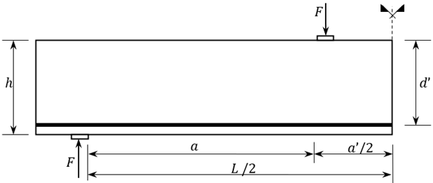
Fig. 1. Simple beams of Leonhard & al. [24] experiments
The geometrical and material data for these beams are given in Table 1.
Table 1. Data for Leonhard’s & al. [24] beams
|
Name |
Cross section |
Shear span $a \, [\text{mm}]$ |
Material data |
|||
|
Hight $h$ effective hight $d' \, [\text{mm}]$ |
Width $b \, [\text{mm}]$ |
$f_c \, [\text{MPa}]$ |
$E \, [\text{MPa}]$ |
$\rho \, [\%]$ |
||
|
Beam1 |
320/270 |
190 |
270 |
35,5 |
33700 |
0,207 |
|
Beam2 |
320/270 |
190 |
400 |
35,5 |
33700 |
0,207 |
|
Beam3 |
320/270 |
190 |
540 |
35,5 |
33700 |
0,207 |
|
Beam4 |
320/270 |
190 |
670 |
35,5 |
33700 |
0,207 |
|
Beam5 |
320/270 |
190 |
810 |
35,5 |
33700 |
0,207 |
|
Beam6 |
320/270 |
190 |
1100 |
35,5 |
33700 |
0,207 |
|
Beam7 |
320/270 |
190 |
1350 |
37,2 |
33700 |
0,201 |
|
Beam8 |
320/270 |
190 |
1620 |
37,3 |
33700 |
0,201 |
|
Beam9 |
320/270 |
190 |
1890 |
38,2 |
33700 |
0,204 |
|
Beam10 |
320/270 |
190 |
2160 |
36,1 |
33700 |
0,205 |
The second series of beams are again simple beams, but with the presence of an initial notch. These beams are taken from real experiments performed by Carmona, Ruiz, del Viso and presented in [25]. General geometry and data are shown in Fig. 2:
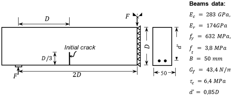
Fig. 2. Simple notched beams
The beams presented in Fig. 2 are divided into three groups according to their size and named with the letter’s "S", $L$ and $M$, see [25]. The $S$ beams are of size $D = 75 \, \text{mm}$. The $M$ beams are of size $D = 150 \, \text{mm}$. The $L$ beams are of size $D = 300 \, \text{mm}$. A different number of rods, each with a diameter of $2.5 \, \text{mm}$, were used as longitudinal reinforcement. The first digit in the name of the beam corresponds to the number of bars of the longitudinal reinforcement, and the second digit $O$ corresponds to the transverse reinforcement, see [25]. In the present study, only beams with longitudinal reinforcement are considered. The beams are non-shear reinforced. Geometric data of these beams are presented in Table 2.
These beams were chosen for several reasons. First the presence of a notch and data on tensile strength and failure energy as difference with Leonhardt’s beams. Second, the change in their dimensions and the change in the reinforcement ratio. In Leonhardt’s beams, there is only a change in the shear span, but not in their height. On the other hand, the beams studied by Carmona, Ruiz, del Viso are of a small scale according to the real beams and Leonhardt’s beams. With these many different characteristics, the author of the present study aimed to examine the model under a variety of conditions.
One drawback of the experimental results for Leonhardt beams is the fact that no data is present on the tensile strength of the concrete and even less on the fracture energy of the material. For this reason, a standard value of fracture energy ($G_f = 90 \, \text{N/mm}$) and tensile strength ($f_t = 3.4 \, \text{MPa}$) of the concrete was adopted to obtain results for the load-carrying capacity of these beams.
Table 2. Geometric data
|
Name |
$\rho$ |
$d \, [\text{mm}]$ |
$d' \, [\text{mm}]$ |
$a \, [\text{mm}]$ |
$b \, [\text{mm}]$ |
|
$S_{10}$ |
0,0013 |
75 |
63,75 |
150 |
50 |
|
$S_{20}$ |
0,0026 |
75 |
63,75 |
150 |
50 |
|
$M_{10}$ |
0,00065 |
150 |
127,5 |
300 |
50 |
|
$M_{20}$ |
0,0013 |
150 |
127,5 |
300 |
50 |
|
$M_{40}$ |
0,0026 |
150 |
127,5 |
300 |
50 |
|
$L_{10}$ |
0,00032 |
300 |
255 |
600 |
50 |
|
$L_{20}$ |
0,00065 |
300 |
255 |
600 |
50 |
|
$L_{40}$ |
0,0013 |
300 |
255 |
600 |
50 |
|
$L_{80}$ |
0,0026 |
300 |
255 |
600 |
50 |
On the other hand, for the original model of Bažant and Yu, values for $d_o$ equal to 100 and 200 mm were used for the individual beams, as was done in the previous study with this model, see [11, 12].
On Table 3 the results for the load-carrying capacity of the beams, calculated by the modified in the present work formula, by the original model of Bažant and Yu, and the experimental data for the beams, are presented.
Table 3. Load-carrying capacity results.
|
Beam |
Load-carrying capacity $V_u \, [\text{kN}]$ |
Difference [%] |
|||
|
Modified model |
Bažant and Yu model |
Experimental results |
Modified model vs Experiment |
Bažant and Yu model vs Experiment |
|
|
$S_{10}$ |
4,50 |
4,60 |
2,5 |
82 |
84 |
|
$S_{20}$ |
5,83 |
5,96 |
4,3 |
37 |
39 |
|
$M_{10}$ |
5,72 |
6,02 |
4 |
44 |
50 |
|
$M_{20}$ |
7,42 |
7,80 |
5,3 |
41 |
47 |
|
$M_{40}$ |
9,63 |
10,12 |
8,1 |
20 |
25 |
|
$L_{10}$ |
6,86 |
7,38 |
6,2 |
12 |
19 |
|
$L_{20}$ |
8,94 |
9,63 |
8 |
13 |
20 |
|
$L_{40}$ |
11,60 |
12,49 |
10 |
17 |
25 |
|
$L_{80}$ |
15,04 |
16,20 |
16 |
5 |
1 |
|
$\text{Beam1}$ |
111,28 |
102,88 |
396 |
72 |
74 |
|
$\text{Beam2}$ |
93,20 |
86,16 |
265 |
65 |
67 |
|
$\text{Beam3}$ |
83,46 |
77,16 |
150 |
44 |
49 |
|
$\text{Beam4}$ |
78,06 |
72,17 |
85,9 |
9 |
16 |
|
$\text{Beam5}$ |
74,19 |
68,59 |
69,8 |
6 |
2 |
|
$\text{Beam6}$ |
69,30 |
64,07 |
65,8 |
5 |
3 |
|
$\text{Beam7}$ |
69,43 |
64,12 |
61,1 |
14 |
5 |
|
$\text{Beam8}$ |
67,54 |
62,38 |
62,4 |
8 |
0 |
|
$\text{Beam9}$ |
66,24 |
61,21 |
56,4 |
17 |
9 |
|
$\text{Beam10}$ |
63,29 |
58,50 |
52,2 |
21 |
12 |
It can be seen from Table 3 that the values $V_u$ obtained with the modified formula are not significantly different from those obtained with the original one. It can be concluded that the proposed modification does not deteriorate the original model.
One can see that for the small beams (in the two series) there is a difference between the experimental data and the size effect formulas. These beams have a rather ductile behaviour, which is the most like reason why they cannot be modelled by the Bažant and Yu model.
Regarding the Leonhardt et al. beams series (see Table 1), a slight deterioration of the results obtained by the modified formulation of the Bažant and Yu model can be seen. A major reason for this is the lack of data on concrete tensile strength and failure energy.
4 Conclusions
As a conclusion of the presented research, it can be said that the introduced modification of the Bažant and Yu model has grounds to be used. The proposed modification does not deteriorate the original model. The modified formulation as well as the original one show lack of accuracy in the case of small beam size which appears to be a limitation for present model. Further study is necessary to investigate this limitation. More experiments extract data on the fracture energy of concrete. This leads to the possibility to include the fracture mechanics parameters in the design formulas. The present results show that including such parameters gives good enough results and it is convenient to include them in the size effect formulas. For to establish it’s the correctness further investigation and calculations are needed. Further developments and modifications are needed to improve the scope of the presented formulation for small beams.
Acknowledgements
No funding was received.
References
- Bažant, Z. P., & Kazemi, M. T. (1991). Size effect on diagonal shear failure of beams without stirrups. ACI Structural Journal, 88(3), 268–276. http://www.concrete.org/PUBS/JOURNALS/SJHOME.ASP
- Zararis, P. D., & Papadakis, G. C. (2001). Diagonal shear failure and size effect in RC beams without web reinforcement. Journal of Structural Engineering, 127(7), 733–742. https://doi.org/10.1061/(ASCE)0733-9445(2001)127:7(733)
- Bažant, Z. P., & Planas, J. (1998). Brittleness and size effect in structural design. In Fracture and size effect in concrete and other quasibrittle materials (pp. 319–360). CRC Press.
- Karihaloo, B. L. (1995). Application to reinforced concrete structures. In Fracture mechanics & structural concrete (pp. 240–276). Longman Scientific & Technical.
- Shah, S. P., Swartz, S. E., & Ouyang, C. (1995). Application of fracture mechanics to concrete structures. In Fracture mechanics of concrete: Applications of fracture mechanics to concrete, rock and other quasibrittle materials (pp. 347–425). John Wiley & Sons.
- Hillerborg, A. (1988). Application of fracture mechanics to concrete – summary of a series of lectures 1988 (Report TVBM-3030). Division of Building Materials, Lund University.
- Nielsen, M. P. (1990). An energy balance crack growth formula. Bygningsstatiske Meddelelser, 61(3–4), 1–125.
- An, X., Maekawa, K., & Okamura, H. (1997). Numerical simulation of size effect in shear strength of RC beams. Journal of Materials, Concrete Structures, Pavements, 564, 297–316.
- Xu, X. P., & Needleman, A. (1994). Numerical simulations of fast crack growth in brittle solids. Journal of the Mechanics and Physics of Solids, 42, 1397–1434. https://doi.org/10.1016/0022-5096(94)90003-5
- Hoang, L. C. (2001). Extension and applications of the crack sliding model. Bygningsstatiske Meddelelser, 72(4), 71–118.
- Bažant, Z. P., & Yu, Q. (2005). Design against size effect on shear strength of reinforced concrete beams without stirrups: Part I. Formulation. Journal of Structural Engineering, 131(12), 1877–1885. https://doi.org/10.1061/(ASCE)0733-9445(2005)131:12(1877)
- Bažant, Z. P., & Yu, Q. (2005). Design against size effect on shear strength of reinforced concrete beams without stirrups: Part II. Verifications and calibrations. Journal of Structural Engineering, 131(12), 1886–1897. https://doi.org/10.1061/(ASCE)0733-9445(2005)131:12(1886)
- Bentz, E. C., & Collins, M. P. (2006). Development of the 2004 Canadian Standards Association (CSA) A23.3 shear provisions for reinforced concrete. Canadian Journal of Civil Engineering, 33(5), 521–530. https://doi.org/10.1139/l06-015
- Kazemi, M. T., & Broujerdian, V. (2006). Reinforced concrete beams without stirrups considering shear friction and fracture mechanics. Canadian Journal of Civil Engineering, 33(2), 161–168. https://doi.org/10.1139/l05-107
- Dönmez, A., & Bažant, Z. P. (2017). Size effect on punching strength of reinforced concrete slabs with and without shear reinforcement. ACI Structural Journal, 114(4), 875–886. https://doi.org/10.14359/51689719
- Christianto, D., Makarim, C. A., Tavio, T., & Jusuf, A. H. (2022). A proposed formula for predicting size effect on shear strength of concrete beams without coarse aggregate. International Journal on Engineering Applications, 10(3), 220–226. https://doi.org/10.15866/irea.v10i3.20552
- Nelson, L. A., Lees, J. M., & Weekes, L. (2022). Size effects in unreinforced and lightly reinforced concrete beams failing in flexure. Engineering Fracture Mechanics, 259, 107987. https://doi.org/10.1016/j.engfracmech.2021.107987
- Cunbao, L., Dongchao, Y., Heping, X., Li, R., & Jun, V. (2023). Size effect of fracture characteristics for anisotropic quasi-brittle geomaterials. International Journal of Mining Science and Technology, 33(2), 201–213. https://doi.org/10.1016/j.ijmst.2022.11.004
- Ashour, A. F., & Kara, I. F. (2014). Size effect on shear strength of FRP reinforced concrete beams. Composites Part B: Engineering, 60, 612–620. https://doi.org/10.1016/j.compositesb.2013.12.002
- Ren, D., & Houben, L. (2020). Determination of fracture energy of early age concrete through a uniaxial tensile test on an un-notched specimen. Materials, 13(3), 496. https://doi.org/10.3390/ma13030496
- Ulfkjær, J. P., Bache, H. H., Brincker, R., & Sørensen, N. B. (1995). Fracture energy of normal strength concrete and ultra high strength ultra ductile steel fiber reinforced concrete. In Proceedings of the 2nd International FRAMCOS Conference.
- Darwin, D., Barham, S., Kozul, R., & Luan, S. (2001). Fracture energy of high-strength concrete. ACI Materials Journal, 98(5), 410–417.
- Yip, C. L., Mohamad, H. M., & Ahmad, H. (2023). Fracture energy measurement in different concrete grades. International Journal of Integrated Engineering, 15(2), 143–150. https://doi.org/10.30880/ijie.2023.15.02.014
- Lee, J., & Lopez, M. M. (2014). Experimental study on fracture energy of plain concrete. International Journal of Concrete Structures and Materials, 8(2), 129–139. https://doi.org/10.1007/s40069-014-0068-1
- Leonhardt, F., & Walther, R. (1962). Schubversuche an einfeldrigen Stahlbetonbalken mit und ohne Schubbewehrung. Deutscher Ausschuss für Stahlbeton.
- Carmona, J., Ruiz, G., & del Viso, J. (2007). Mixed-mode crack propagation through reinforced concrete. Engineering Fracture Mechanics, 74, 2788–2809. https://doi.org/10.1016/j.engfracmech.2007.01.005
Conflict of Interest Statement
The author declares that there is no conflict of interest regarding the publication of this paper.
Author Contributions
Data Availability Statement
All data is publicly available from cited web sources.
Supplementary Materials
No supplementary materials are available.