Received: Oct 08, 2024 Accepted: Apr 07, 2025 Available Online: Jul 21, 2025 Published: Apr 23, 2025
DOI: 10.5937/jaes0-54004
EXPERIMENTAL AND NUMERICAL STUDY FOR FREE VIBRATION ANALYSIS OF SANDWICH PLATES WITH CUTOUT
Abstract
In this paper, free vibration assessments of sandwich plates with a square, triangle, and circle cutouts were performed both theoretically and practically. Cutouts are inescapable in structural applications, and their presence significantly affects the structure's dynamic qualities. A finite element model was created with ANSYS software to investigate the vibration properties of sandwich plates with cutouts. The model's development takes into account the Shell 292 element, a 12-noded element with six degrees of freedom that may be used to examine various fixed edge configurations. The natural frequencies and mode shapes of the sandwich structure were determined for various edge numbers.
Highlights
- Free vibration assessments of sandwich plates with a square, triangle, and circle cutouts were performed both numerically and practically.
- A finite element model was created with ANSYS software to investigate the vibration properties of sandwich plates with cutouts.
- The parametric investigation demonstrated that the sandwich plate's natural frequency is greatly influenced by the boundary conditions and cutout designs.
Keywords
Content
1 Introduction
These days, sandwich structures are used as structural components in a wide range of engineering applications.
A particular type of laminated construction consisting of a thick flexible core sandwiched between two thin face sheets is called a sandwich structure. Generally, a sandwich structure typically consists of two thin, stiff face sheets bonded to a thicker, lightweight core material; the face sheets are made of high-strength materials like fiber-reinforced composites or metal [1, 2]. The structure's moment of inertia is greatly increased by the face sheets' spacing, yet it is kept light by the thick layer of low-density core [3]. Cutouts are frequently required in structural applications, for example, to facilitate utility services such as fuel, hydraulic, or electrical lines, to provide access to other areas of the structure, to lower the overall structure's weight, and so on. The dynamic features of buildings are considerably altered by cutouts, which has piqued the interest of academics for further investigation [1, 3]. Sivakumar et al. [4] used FEA to investigate the composite plates' vibrational characteristics with incisions subjected to high-amplitude vibrations. The Ritz finite element method is used to create the model, which consists of nine nodded c0 continuous quadrilateral elements with higher-order displacement fields. The hypothesis describes a parabolic change in transverse shear stress. The results regarding the plate's dynamic behavior under different parameter adjustments are shown. Ju et al. [5] measured the vibration of composite square and circular plates with delamination surrounding the cutout to investigate how the cutout affected natural frequencies and mode shapes. Liew et al. [6] carried out a computational analysis of the plate vibration with central cutouts that cause internal discontinuities. The formulation ensures that the higher derivatives, displacement, slope, and moment between neighboring subdomains are continuous. The ridge technique is used to determine the vibration frequency. Niranjan Kumar et al. [7] developed a three-dimensional, elasticity-based finite element model to investigate a composite plate static behavior that has a cutout in the center.
Different parametric variations are used to derive interlaminar stress, plane stress, and transverse deflections. Experimental techniques were employed by Riyah et al. [8] to study the laminate plate with a cutout's static behavior. Barut et al. [9] used a simplified {3, 0}-plate theory to provide an analytical method for stress analysis and buckling of laminated plates that have been sliced. According to the theory, there will be no transverse shear forces on the laminate faces. The formulation relies on displacement fields' cubical fluctuation. Boay [10] utilized FEA and experimental data to investigate the vibration of symmetric composite plates with a circular hole. Bharadwaj et al. [11] computed the composite plates with cutouts vibrational responses. Code written in the ANSYS parametric design language (APDL) is used to do the finite element analysis. The effects of different geometric factors (thickness ratio, aspect ratio, number of layers, boundary conditions, angle of lamina geometry of cutout, distance between cutouts, and cutout side-to-plate side ratio) and material qualities on free vibration responses are thoroughly analyzed. Using the FEA approach, Bhatt et al. [12, 13] looked into the characteristics of a composite plate with a cutout. The publicly accessible ANSYS software was used to conduct the FEA. For static vibration, free bending, sandwich functionally graded microplates and buckling investigations of isotropic, a size-dependent shear deformable model is presented, and it is based on the modifications of strain gradient theory [14]. A unique displacement for the FGM sandwich plate's static response is created based on four variable high-order deformation [15]. Using a Fourier series solution, three-dimensional static and free vibration measurements are conducted for a simply mounted FGM sandwich rectangular plate [16].
The new theory of hyperbolic shear and normal deformation plates is simple to understand and useful for predicting the mechanical characteristics of FGM sandwich plates. Served as the basis for Akavci's [18] investigation of a model for static, free vibration, and buckling examination of simply mounted functionally evaluated sandwich plates on flexible foundations.
The thorough literature review indicates that while a great deal of productive research has been done to understand the behavior of laminated composite plates with cutouts, more has to be done to investigate sandwich plate analysis with cutouts. The investigation will be conducted using the finite element modeling program ANSYS 15.0, and ANSYS parametric design language (APDL) codes have been utilized to examine the behavior of sandwich plates with cuts in them. The sandwich plates consist of a PVC foam core and stainless-steel face sheets. The influence of various factors on the vibration characteristics of sandwich plates with cutouts is investigated theoretically and practically. This vibration characteristics analyzed are natural frequencies and mode shapes under varying boundary conditions (CFFF, CFCF, CCCC) and cutout shapes (square, triangle, circle). Where (CFFF: Clamped-Free-Free-Free, CCCC: Clamped-Clamped-Clamped-Clamped, and CFCF: Clamped-Free-Clamped-Free).
2 Materials and methods
The sandwich plate coordinate system comprises one global Cartesian coordinate system, and three local Cartesian coordinate systems. The sandwich plate's central plane is represented by the plane z = 0 in the global Cartesian coordinate system. The mathematical approach was designed to manage sandwich plates with soft and operationally graded centers in their slices [19, 20].
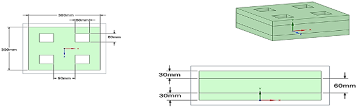
Using the hand-layup approach, symmetric Sandwich specimens with three separate layers and viscoelastic cores are made. The sandwich plates are rectangular in shape and consist of a PVC core layer and two stainless steel facing layers. Tables 1 and 2 present the model's shape and material attributes. The glue that holds the layers together is araldite. The sandwich plates are manually cured for three days at room temperature by being subjected to constant pressure. The specimens' surfaces are washed with acetone to remove any impurities once they have cured. A Vernier caliper is used to measure the thickness of the artificial samples in order to guarantee accuracy. The measurement is taken three times at different places to ensure uniformity. The average of these values is then determined [21].
Using a cutter with a diamond-impregnated wheel, cutouts of various sizes in the shapes of circles, triangles, and squares are made on the manufactured sandwich plates at the desired locations. For every distinct cutout configuration, three samples are made and put through modal testing in order to reduce experimental mistakes. It has been discovered that the variance in the outcomes of the individual experiment samples is less than 1.5%, indicating the findings' consistency and repeatability and, thus, the validity of the experimental design.
ANSYS 15.0 software is used to model the sandwich plate in order to do the dynamic analysis with cutout. The structure is modeled using the 12-nodded Shell 292 element, which has six degrees of freedom at each node [22]. Layered applications may replicate composite and sandwich structures, and they are suitable for examining structures that range in thickness from thin to considerable. The mode forms are extracted using the Block Lanczos approach, which also identifies the natural frequency corresponding to the plate's free vibration.
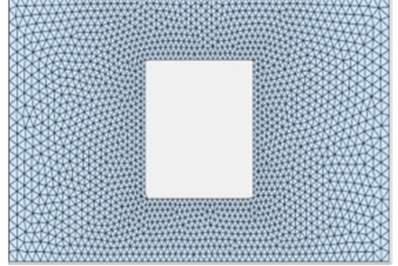
The sandwich plate's triangular element mesh features many cutout shapes created using the ANSYS toolbox. As the mesh sizes get closer to the cutout, the mesh-generating software progressively fine-tunes them. Fig.1 displays the produced meshes for the various cutout forms. In addition, Fig. 2 shows the sandwich plate's geometry and coordinate system for various cutouts (square, triangle, and circular). For every form, the same initial mesh refinement value, mesh refinement distribution between inner and outer bounds, and other algorithmic settings apply [23, 24].
Table 1. Characterization of upper and lower plates.
| Stainless Steel | |
| Structural | |
| Isotropic Elasticity | |
| Derive from | Young's Modulus and Poisson's Ratio |
| Young's Modulus | 1.93e+05 MPa |
| Poisson's Ratio | 0.31 |
| Bulk Modulus | 1.693e+05 MPa |
| Shear Modulus | 73664 MPa |
| Isotropic Secant Coefficient of Thermal Expansion | 1.7e-05 1/°C |
| Compressive Ultimate Strength | 0 MPa |
| Compressive Yield Strength | 207 MPa |
| Tensile Ultimate Strength | 586 MPa |
| Tensile Yield Strength | 207 MPa |
Table 2. Characterization of middle plate (core)
| PVC Foam (60 kg m^-3) | |
| Structural | |
| Isotropic Elasticity | |
| Derive from | Young's Modulus and Poisson's Ratio 70 MPa |
| Young's Modulus | 70 MPa |
| Poisson's Ratio | 0.3 |
| Bulk Modulus | 58.333 MPa |
| Shear Modulus | 26.923 MPa |
| Orthotropic Stress Limits | |
| Tensile X direction | 1.5 MPa |
| Tensile Y direction | 1.5 MPa |
| Tensile Z direction | 0.95 MPa |
| Compressive X direction | -1.5 MPa |
| Compressive Y direction | -1.5 MPa |
| Compressive Z direction | -0.95 MPa |
(a)

(b)

(c)
Fig. 1. Mesh creation using triangle components for a variety of cutouts (a) square, (b) triangle and (c) circular
(a)

(b)
![]()
(c)
Fig. 2. Sandwich plate geometry and coordinate system for a variety of cutouts (a) square, (b) triangle and (c) circular
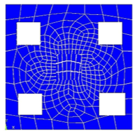
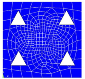
The number of natural frequencies in a structure is determined by its complexity and degrees of freedom. In structural dynamics, natural frequencies correspond to a structure's vibrational modes. Each vibrational mode corresponds to a certain natural frequency [23]. A basic structure, such as a mass-spring system, has only one natural frequency. However, more complicated structures with several degrees of freedom, such as buildings, bridges, or mechanical systems, may have multiple natural frequencies. Fig. 3 shows a common sandwich plate model with cutouts in the shapes of a square, triangle, and circle.
(a)

(b)
(c)
Fig. 3. Sandwich plate FE model using ANSYS for a variety of cutouts: (a) square, (b) triangle and (c) circular
The experimental study is done to find the modal features of sandwich plates with and without cutouts. The samples are prepared, and cutouts of different sizes and shapes are positioned fixedly on the samples. These specimens are subjected to free vibration testing to ascertain their damping properties and dynamic responses. For various boundary circumstances, the modal characteristics of sandwich plates with and without cutouts are ascertained using the impact hammer modal testing method. An IEPE speedometer (Bruel and Kjaer 4507), an instrument hammer (Bruel and Kjaer 8206–002), computers with modal evaluation programs, and the fast Fourier transform (FFT) analyzer (Bruel and Kjaer 3560-C) were among the tools employed in the present modal testing technique. The software tools for modal analysis, ME 'scope and Pulse Lab shop, are used for experimental modal analysis. First, the specimen is laid out horizontally on the iron frame that has already been erected. The edges are then secured with nuts and bolts in accordance with the necessary boundary conditions. The FFT analyzer is linked to the corresponding channel of the modal hammer and accelerometer. A computer is then connected to the FFT analyzer to do data analysis. The roving hammer method is used to detect vibrations in which the test specimen is activated by striking the modal hammer at many predetermined points while the accelerometer is stationary in one place. The reaction brought on by the modal hammer's impact is detected by the accelerometer fastened to the sandwich plate. The Pulse Lab shop platform is used by the FFT analyzer to operate. It generates the modal analysis's input FRFs. With ME 'scope software, the recorded data is post-processed to identify the sandwich plate's modal properties. To minimize the chance of experimental error, each sample is tested four times, and the average vibration result is taken into account. The modal damping related to a particular eigenmode is computed using the half-power bandwidth approach.
(a)
(b)
(c)
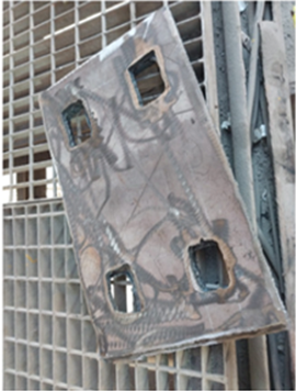
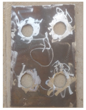
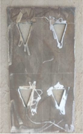
Fig. 4. Photographic view of the sandwich plate for a variety of cutouts (a) square, (b) triangle and (c) circular
It should be clarified that there are some limits in the experimental approach, such as (1) the impact hammer method has limitations in exciting higher frequency modes; (2) perfect boundary conditions are difficult to achieve in practice, leading to possible differences between theoretical and experimental results; and (3) environmental factors such temperature and humidity variations may affect material properties. On the other hand, limitations of the numerical technique include (1) the presumption of perfect bonding between layers, (2) linear elastic material behavior assumptions, and (3) disregarding damping effects in the frequency analysis.
3 Results and discussion
The sandwich plate with the cutout has its free vibration response calculated using the proposed model. To evaluate the accuracy of the ANSYS model generated here, the findings are first confirmed by comparing them to the experimental results of a comparable sandwich plate. The vibration test was conducted using the impact hammer method at room temperature, and the plate was fitted in accordance with the necessary boundary conditions [24, 25]. The first eight theoretical and experimental vibration damping characteristics for sandwich plates without cutouts are listed in Table 3 regarding CFFF, CCCC, and CFCF boundary conditions. The outcomes show a high degree of agreement between theoretical and practical outcomes, attesting to the efficacy of the FE model put forward in this study. All vibration modes have the minimum natural frequency in the sandwich layer with the CFFF boundaries condition. They are, in ascending sequence, CFCF and CCCC.
Table 3. The first eight Practical and theoretical frequencies of a sandwich plate without cutout are examined for various boundary circumstances
| No. of modes | CFFF | CFCF | CCCC | |||
| ANSYS | Practical | ANSYS | Practical | ANSYS | Practical | |
| 1 | 36 | 35.0992 | 140 | 134.4678 | 484 | 490.5617 |
| 2 | 110 | 108.3847 | 228 | 218.3774 | 642 | 660.7361 |
| 3 | 148 | 146.9358 | 368 | 354.3538 | 928 | 957.5773 |
| 4 | 198 | 196.4683 | 467 | 445.6376 | 1489 | 1534.674 |
| 5 | 267 | 264.9366 | 678 | 662.7484 | 1920 | 1978.436 |
| 6 | 398 | 390.64743 | 925 | 904.6875 | 2346 | 2395.436 |
| 7 | 428 | 416.34521 | 1248 | 1223.348 | 2892 | 2935.153 |
| 8 | 537 | 515.3764 | 1640 | 1605.135 | 3378 | 3455.647 |
Where C is clamped, and F is free. Experiments and theoretical calculations are used to identify the eight natural frequency modes of the test plate with varying form cutouts for different boundary circumstances. These are shown in Table 4. Figure 5 also shows a graphical depiction of the vibrational properties for the experimental first three eigenmodes when compared to the sandwich plate without and with a various cutout for variable boundary condition.
Consequently, adding the cutout causes the frequency to rise. Since the midsection of the CCCC boundary conditions has a low-stress zone, the location of a circular cutout has no influence on stiffness. Mass reduction, therefore, has a significant role in raising the frequency of the CCCC border circumstances. Stress is lowest in the free end region and highest in the plate area closest to the support under the CFFF boundary condition. As a result, the stiffness reduction generated by the cutout's insertion determines whether natural frequency increases or decreases.
Table 4. The first eight actual and theoretical natural frequencies of the sandwich plate with cutout were compared in a variety of boundary conditions
| Cutout Shape | Mode No. | CFFF | CFCF | CCCC | |||
| ANSYS | Experimental | ANSYS | Experimental | ANSYS | Experimental | ||
| Circle | 1 | 32 | 33.9204 | 148 | 141.8413 | 538 | 546.9367 |
| 2 | 96 | 99.7274 | 218 | 211.5248 | 614 | 622.0473 | |
| 3 | 136 | 143.9262 | 350 | 336.5466 | 984 | 1080.8172 | |
| 4 | 190 | 191.3784 | 417 | 398.6376 | 1536 | 1504.674 | |
| 5 | 254 | 258.1848 | 613 | 582.7484 | 2120 | 1198.436 | |
| 6 | 377 | 382.6737 | 847 | 807.6875 | 2462 | 2545.436 | |
| 7 | 405 | 409.5784 | 1123 | 1085.348 | 2915 | 3075.153 | |
| 8 | 502 | 510.3764 | 1428 | 1382.135 | 3550 | 3649.647 | |
| Square | 1 | 30 | 31.8759 | 144 | 139.1445 | 534 | 543.1179 |
| 2 | 94 | 95.1482 | 212 | 209.6472 | 610 | 616.8954 | |
| 3 | 134 | 138.1257 | 346 | 332.1240 | 980 | 1066.1174 | |
| 4 | 187 | 194.4683 | 467 | 445.6376 | 1575 | 1634.674 | |
| 5 | 255 | 264.9366 | 678 | 662.7484 | 2124 | 2178.436 | |
| 6 | 374 | 386.64743 | 925 | 904.6875 | 2443 | 2495.436 | |
| 7 | 408 | 416.34521 | 1248 | 1223.348 | 2970 | 3135.153 | |
| 8 | 517 | 524.3764 | 1640 | 1605.135 | 3559 | 3585.647 | |
| Triangle | 1 | 28 | 30.1471 | 142 | 138.1181 | 530 | 536.4713 |
| 2 | 90 | 93.1656 | 210 | 206.1319 | 608 | 614.1478 | |
| 3 | 130 | 135.5792 | 344 | 330.8756 | 976 | 1055.196 | |
| 4 | 180 | 188.4683 | 462 | 448.6376 | 1465 | 1634.674 | |
| 5 | 245 | 259.5875 | 675 | 662.7484 | 2088 | 2178.948 | |
| 6 | 366 | 379.4356 | 918 | 904.6875 | 2413 | 2495.484 | |
| 7 | 389 | 406.3353 | 1230 | 1223.348 | 2874 | 2985.747 | |
| 8 | 504 | 529.5467 | 1622 | 1605.135 | 3489 | 3535.737 | |
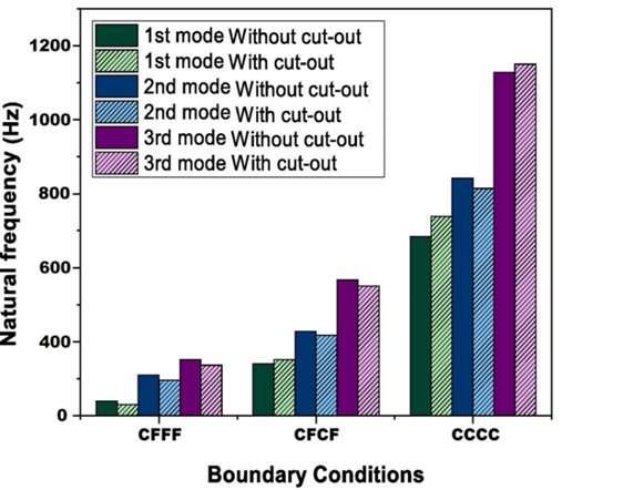
Fig. 5. Experimentally measured frequeny with and without cutouts under boundary conditions
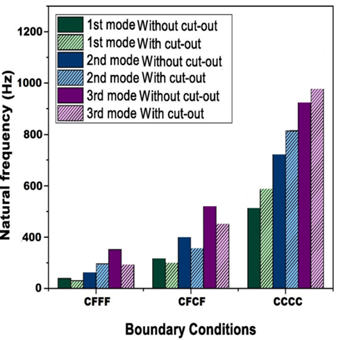
Fig. 6. Numerically (ANSYS) calculated frequency of sandwich plates under various boundary conditions, both with and without cuts
Additionally, figure 6 graphically compares the vibrational characteristics of the ANSYS first three eigenmodes to sandwich plates with and without different cutouts. It is important to remember that the mass and stiffness of the structure have a reciprocal relationship with its frequency. Consequently, the presence of cutouts in the structure may cause the natural frequency to change. It will determine if "rigidity motion" or "mass movement" is more prevalent. The least amount of stiffness is achieved when the cutout is placed in the area of least stress. As mass diminishes, dominant mass action takes over. Consequently, adding the cutout causes the frequency to rise. There is no change in stiffness when a circular cutout is inserted because there is still a low-tension zone in the midst of the CCCC border condition. Therefore, increasing the frequency of the CCCC boundary circumstances is mostly dependent on mass reduction. For the CFFF boundaries condition, stress is lowest at the free end area and greatest in the surface area next to the support. Therefore, whether natural frequency rises or falls relies on the decrease in stiffness caused by the cutout's insertion.
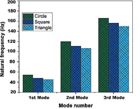
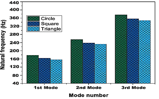
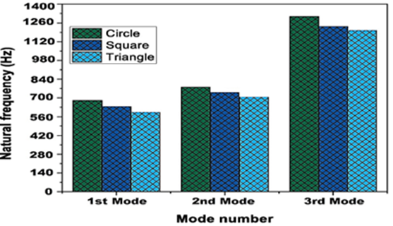
Several characteristics can influence the frequency of a plate with cutouts, including the design, size, and position of the cuts. Carefully weighing these factors is essential when building sandwich plates with cutouts for certain applications. For experimenting, cutouts in the shapes of triangles, squares, and circles are produced at preset sandwich plate locations and sizes. Figures 7(a), 7(b), and 7(c) illustrate how cutout shapes affect sandwich plate-free vibration and damping capacity.
(a)
(b)
(c)
Fig. 7. The influence of the cutout form on the frequency of sandwich plates under CFFF boundary conditions
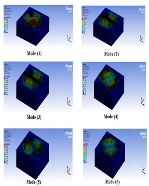
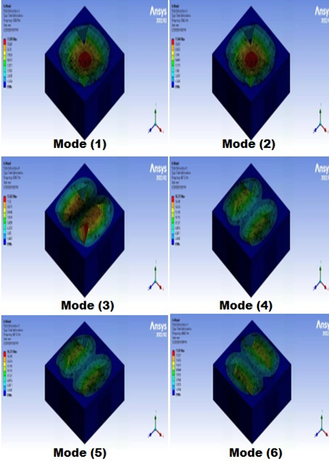
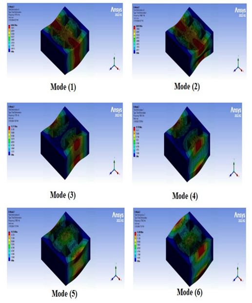
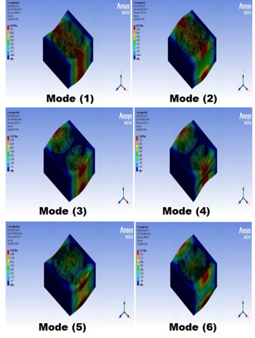
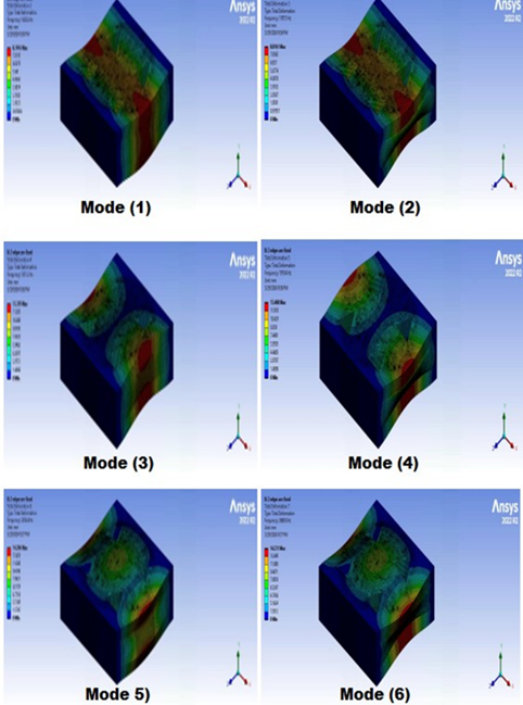
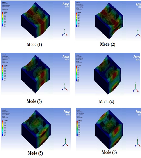
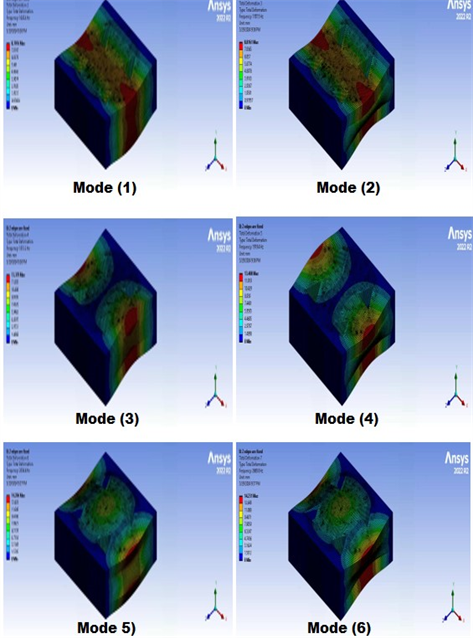
It is critical for the design to understand the mode shapes and vibration frequency values in the event of free vibration in engineering structures. Table 5 shows the frequencies in the first six modes for all fixed edges and two fixed edges for square cutout. The frequency for all fixed edges for square, circle, and triangle may be seen in Fig.8 (a), Fig.8 (b), and Fig.8 (c). The frequencies for two fixed edges for square, circle, and triangle have been shown in Fig.9 (a), Fig.9 (b), and Fig.9 (c). Also, the frequencies for no fixed edges for square, circle, and triangle have been shown in Fig.10 (a), Fig.10 (b), and Fig.10 (c). The colored contours in these figures represent the normalized total displacement distribution for each mode shape, with red indicating maximum displacement and blue indicating minimum displacement. These contours represent the complete deformation that occurs when an external force applies to the structure, causing the resultant frequency to equal the structure's inherent frequency. The impact of modifying the fixed edges on free vibration is as follows: Although there is a general fall in frequency as the fixed edges rise, this is not drastic, and in some modes, it may even increase. As a result, it would be more accurate to study each mode individually. The number of edges in the core has increased significantly, increasing the frequency of the sandwich structure. This was linked to an excessive growth in the number of edges. It should be noted that modes 2 and 5 are contradictory to the typical scenario. When the modes are compared, mode 1 has the lowest frequency value for all three sandwich forms, while mode 6 has the highest. The frequency values of the sandwich structure grow as the modes continue.
Table 5. Free vibration frequencies of sandwich structures
| SandwichStructures (SS) | ANSYS | Experimental | ||
| All fixed edges | Two fixed edges | All fixed edges | Two fixed edges | |
| Mode (1) | 2428.9 | 1575.5 | 2430.6 | 1576 |
| Mode (2) | 2485.7 | 1664.7 | 2486.5 | 1665.4 |
| Mode (3) | 4849.6 | 1791 | 4850.85 | 1792.3 |
| Mode (4) | 4849.6 | 1861.2 | 4851.2 | 1862 |
| Mode (5) | 4867.2 | 2700.5 | 4868.8 | 2701.2 |
| Mode (6) | 4867.2 | 2736.3 | 4878 | 2737 |
(a)

(b)
(c)
Fig. 8. (a) The initial six sandwich construction modes form for every fixed edge square cutout, (b) The initial six sandwich construction modes form for every fixed edge circle cutout and (c) The initial six sandwich construction modes form for every fixed edge triangle cutout
(a)
(b)
(c)
Fig. 9. (a) The first six sandwich structure mode forms with just two fixed edges square cutouts, (b) The first six sandwich structure mode forms with just two fixed edges circle cutouts and (c) The first six sandwich structure mode forms with just two fixed edges triangle cutouts
(a)

(b)
(c)
Fig.10. (a) The first six sandwich structure modes form with no fixed edges square cutout, (b) The first six sandwich structure modes form with no edges circle cutout, and (c) The first six sandwich structure modes form with no edge triangle cutout
The torsional modes were found at the natural frequencies of mode 2 and 5. Only one lateral bending mode exists at the natural frequency of mode 6. Unlike the experimental results, changes in mode patterns between two fixed edges were identified. When Table 4 is thoroughly reviewed, it is clear that some modes alter their behavior. For example, mode 5 was torsional for all fixed edges but became lateral bending for two of them. In another case, with two fixed edges in ANSYS, mode 6 was lateral bending, whereas fixed edges were simply bending.
The frequency values of the sandwich structures in mode 5 have shifted to an insignificant level, comparable to those of mode 6. The mode forms are torsional and lateral bending, which is assumed to account for the small amount of change. The greatest change was found in vertical bending. In general, a structure's natural frequencies match its degrees of freedom. Degrees of freedom are the separate ways in which a structure can move or deform. As a result, every structure with N degrees of freedom will have N natural frequencies.
In practical engineering applications, natural frequency analysis is critical for understanding structures' dynamic behavior and ensuring that they do not resonate with external pressures, which might lead to structural collapse.
4 Conclusions
The analysis shows how the sandwich plate's natural frequency is impacted by the cutout shape. The number of fixed edges has also been studied, and the effect of the free vibration analysis of sandwich plates has been studied. Experimental comparisons with the constructed model support the suggested model's correctness and dependability. The increase in the number of fixed edges resulted in a significant rise in the frequency of sandwich structures (both theoretically and empirically), as well as an effect on the kind of same mode shape. All fixed edges were found to be the most efficient parameter in controlling the natural frequency of the sandwich construction. Vertical bending modes also showed the greatest increase in natural frequency. Other kinds of change, such as torsional and lateral bending, were limited. The current work looks at the vibration behavior of a sandwich plate, focusing on the impacts of cutout form under different boundary circumstances. The modal analysis conducted by experimentation employs the impact hammer method, whereas the theoretical analysis employs the finite element approach. The parametric investigation demonstrated that the sandwich plate's natural frequency is greatly influenced by the boundary conditions and cutout designs. The current study led to the following findings.
- Across the three boundary conditions tested (CFFF, CFCF, and CCCC), the CFFF condition produced the lowest natural frequency values, while the CCCC condition produced the highest natural frequency values.
- Adding a cutout in the sandwich structure alters its vibrational properties by reducing both mass and stiffness. For the CCCC condition, mass reduction dominated, causing increased natural frequency. For the CFFF condition, the stiffness reduction near the clamped edge was the dominant effect, decreasing the natural frequency for all cutout shapes.
- Among the three forms under consideration, the circular cutout configuration produces the greatest natural frequency, whilst the triangle cutout configuration produces the lowest natural frequency under all boundary circumstances.
Acknowledgements
No external funding was received.
References
- Altenbach, H., Altenbach, J., & Kissing, W. (2004b). Mechanics of composite structural elements. In Springer eBooks. https://doi.org/10.1007/978-3-662-08589-9
- Shivakumar, K. N., Argade, S. D., Sadler, R. L., Sharpe, M. M., Dunn, L., Swaminathan, G., & Sorathia, U. (2006). Processing and properties of a lightweight fire-resistant core material for sandwich structures. Journal of advanced materials, 38(1), 32-38.
- Saha, G. C., Kalamkarov, A. L., & Georgiades, A. V. (2007). Effective elastic characteristics of honeycomb sandwich composite shells made of generally orthotropic materials. Composites Part a Applied Science and Manufacturing, 38(6), 1533–1546. https://doi.org/10.1016/j.compositesa.2007.01.002
- Sivakumar, K., Iyengar, N., & Deb, K. (1999). FREE VIBRATION OF LAMINATED COMPOSITE PLATES WITH CUTOUT. Journal of Sound and Vibration, 221(3), 443–470. https://doi.org/10.1006/jsvi.1998.2034
- Ju, F., Lee, H., & Lee, K. (1995). Free vibration of composite plates with delaminations around cutouts. Composite Structures, 31(2), 177–183. https://doi.org/10.1016/0263-8223(95)00016-x
- Liew, K., Kitipornchai, S., Leung, A., & Lim, C. (2003). Analysis of the free vibration of rectangular plates with central cut-outs using the discrete Ritz method. International Journal of Mechanical Sciences, 45(5), 941–959. https://doi.org/10.1016/s0020-7403(03)00109-7
- Mishra, N., Basa, B., & Sarangi, S. K. (2016). Free vibration Analysis of Sandwich Plates with cutout. IOP Conference Series Materials Science and Engineering, 149, 012149. https://doi.org/10.1088/1757-899x/149/1/012149.
- NE, A., & NK, R. (2009). Stress Analysis of Composite Plates with Different Types of Cutouts. Deleted Journal, 2(1), 11–29. https://doi.org/10.37649/aengs.2009.14251
- Barut, A., Madenci, E., & Nemeth, M. P. (2011). Stress and buckling analyses of laminates with a cutout using a {3,0}-plate theory. Journal of Mechanics of Materials and Structures, 6(6), 827–868. https://doi.org/10.2140/jomms.2011.6.827
- Boay, C. G. (1996). Free vibration of laminated composite plates with a central circular hole. Composite Structures, 35(4), 357–368. https://doi.org/10.1016/s0263-8223(96)00037-2
- Bhardwaj, H., Vimal, J., & Sharma, A. (2015). Study of free vibration analysis of laminated composite plates with triangular cutouts. Engineering Solid Mechanics, 3(1), 43-50.
- Bhatt, D., Mishra, Y., & Sharma, P. K. (2014). Model Analysis of Centre Circular Cutout of Laminated Composite Plate and Square Skew Plate by using FEM. International Journal of Engineering Sciences & Research Technology, 3, 8-16.
- Brethee, K. F. (2009). Free vibration analysis of a symmetric and anti-symmetric laminated composite plate with a cutout at the center. Al-Qadisiya Journal for Engineering Sciences, 2(2).
- Thai, C. H., Ferreira, A., & Nguyen-Xuan, H. (2018). Isogeometric analysis of size-dependent isotropic and sandwich functionally graded microplates based on modified strain gradient elasticity theory. Composite Structures, 192, 274–288. https://doi.org/10.1016/j.compstruct.2018.02.060
- Abdelaziz, H. H., Atmane, H. A., Mechab, I., Boumia, L., Tounsi, A., & Abbas, A. B. E. (2011). Static analysis of functionally graded sandwich plates using an efficient and simple refined theory. Chinese Journal of Aeronautics, 24(4), 434–448. https://doi.org/10.1016/s1000-9361(11)60051-4
- Alibeigloo, A., & Alizadeh, M. (2015). Static and free vibration analyses of functionally graded sandwich plates using state space differential quadrature method. European Journal of Mechanics - a/Solids, 54, 252–266. https://doi.org/10.1016/j.euromechsol.2015.06.011
- Li, D., Deng, Z., Xiao, H., & Jin, P. (2017). Bending analysis of sandwich plates with different face sheet materials and functionally graded soft core. Thin-Walled Structures, 122, 8–16. https://doi.org/10.1016/j.tws.2017.09.033
- Akavci, S. (2016). Mechanical behavior of functionally graded sandwich plates on elastic foundation. Composites Part B Engineering, 96, 136–152. https://doi.org/10.1016/j.compositesb.2016.04.035
- Falkowicz, K. (2023). Experimental and numerical failure analysis of thin-walled composite plates using progressive failure analysis. Composite Structures, 305, 116474. https://doi.org/10.1016/j.compstruct.2022.116474
- Zhen, W., Zhengliang, L., Jie, Z., Senlin, Z., Yushan, X., & Xiaohui, R. (2021). A five-variable model and experiments for dynamic analysis of sandwich plates with holes. Mechanics of Advanced Materials and Structures, 29(27), 6312–6329. https://doi.org/10.1080/15376494.2021.1975328
- Falkowicz, K. (2021). Buckling numerical analysis of composite plate element in asymmetrical configuration. Journal of Physics Conference Series, 1736(1), 012029. https://doi.org/10.1088/1742-6596/1736/1/012029
- Kim, Y., & Park, J. (2020). A theory for the free vibration of a laminated composite rectangular plate with holes in aerospace applications. Composite Structures, 251, 112571. https://doi.org/10.1016/j.compstruct.2020.112571
- Atilla, D., Sencan, C., Kiral, B. G., & Kiral, Z. (2020). Free vibration and buckling analyses of laminated composite plates with cutout. Archive of Applied Mechanics, 90(11), 2433–2448. https://doi.org/10.1007/s00419-020-01730-2
- Mandal, A., Ray, C., & Haldar, S. (2019). Experimental and Numerical Free Vibration Analysis of Laminated Composite Plates with Arbitrary Cut-Outs. Journal of the Institution of Engineers (India) Series C, 101(2), 281–289. https://doi.org/10.1007/s40032-019-00537-7
- Venkateshappa, S. C., Kumar, P., & Ekbote, T. (2018). Free vibration studies on plates with central cut-out. CEAS Aeronautical Journal, 10(2), 623–632. https://doi.org/10.1007/s13272-018-0339-7
Conflict of Interest Statement
There are no conflicts affecting the research.
Author Contributions
Data Availability Statement
There is no dataset associated with the study or data is not shared.
Supplementary Materials
There are no supplementary materials to include.