Volume 24 number 1 article 1326 pages: 188-202
Received: May 05, 2025 Accepted: Dec 23, 2025 Available Online: Feb 25, 2026 Published: Mar 02, 2026
DOI: 10.5937/jaes0-58641
PARAMETRIC MODELLING OF BOLTED ASSEMBLY AND ITS COMPONENTS FOR INDUSTRIAL DESIGN AND APPLICATION
Abstract
In the present work is proposed a methodology for parametric modeling of a bolted joint including four separate components, each of which is described with tabular dimensions according to current standard. The parametric model can automatically create a bolted assembly unit with a selected fastening size used for creating metal construction and bigger assemblies. Solutions are performed for the bolted joints used mostly in the industry.
Highlights
- The article presents a parametric CAD methodology in which key geometric and functional parameters (fastener size, thread length, and fixing length) are linked, allowing rapid modification and use of bolted assemblies across different industrial applications.
- By adding constraints and standardized fastener parameters, the proposed model preserves design intent and ensures correct alignment and assembly behavior, reducing modeling errors and design iteration time.
- The parametric bolted assembly could provide efficient coupling with a future finite element analysis (FEA) study for evaluating stress distribution, preload effects, and joint stiffness, making it suitable for early-stage design validation and optimization.
- The approach demonstrates how parametric modeling enhances design automation, standardization, and scalability, supporting faster product customization and collaboration between design and analysis, reducing development costs.
Keywords
Content
1 Introduction
Bolted joints are fundamental in industrial assemblies and all kinds of mechanical constructions, offering reliability, ease of maintenance, and cost-effectiveness. The advent of parametric modeling has revolutionized the design and analysis of these joints, enabling engineers to systematically explore the effects of various design parameters on joint performance. By integrating parametric modeling with finite element analysis (FEA) [1], [2], [3], [4], [5], designers can simulate and optimize bolted connections under diverse loading conditions, enhancing structural integrity and efficiency.
Parametric 3D modeling is a computer-aided design (CAD) technique that involves creating and modifying 3D models using parameters, relationships, and constraints. It allows engineers to build, manipulate, and expand these objects while maintaining control over various design parameters – main and secondary.
Usually, the parameters are used to represent dimensions, orientations, or other characteristics integral to the design of the selected part (assembly). You can define the length, width, height, and various angles of an object as parameters and assign values, formulas, or relationships to each other [6], [7].
Constraints establish relationships and enforce rules that control how certain parts of the model are connected. Common constraints include geometric, dimensional, and assembly constraints. These constraints ensure that the model maintains its shape and relationships as you make changes and improvements. While establishing relationships and constraints can make design easier, it can also limit creativity and design freedom. A complex model with numerous relationships can also become difficult to manage and work with.
Parametric modeling allows designers to create models that are highly flexible and modifiable. This can be useful in design processes where designers make frequent changes that could have a significant impact on the final design [8], [9].
This approach is conducive to iterative design, allowing designers to explore multiple design variations. Parametric modeling can help designers refine and optimize a given 3D model over time [10], [11].
Parametric design can also streamline and automate many tasks, helping to improve the designer’s efficiency and accuracy and to focus on creativity and problem solving. It is widely used in various industries due to its flexibility, efficiency and ability to create complex and adaptive 3D models. Some of the more common applications are: Product design and manufacturing, Architecture, Aeronautics, Automotive, Electrical, Industrial equipment design [12], [13], [14].
These are some of the most widely used applications of parametric modeling, but as creative designers are constantly finding new ways to make the most of the technology, this list is sure to continue to grow.
Some major limitations of parametric modeling include the high learning curve that comes with the process. To take advantage of all the benefits that this process has to offer, a designer needs a good understanding of parametric relationships and constraints and an understanding of how to use and change them effectively.
Finally, designers may consider accessibility as a limitation to consider. Ultimately, there are design tasks that may not be suitable for the parametric modeling approach.
Parametric modeling may involve defining key variables—such as bolt diameter, preload force, material properties, and geometric configurations—that influence the behavior of bolted joints. This approach allows for the creation of adaptable models that can be easily modified to assess different design scenarios [15]. Finite element analysis serves as a powerful tool in this context, providing detailed insights into stress distributions, deformation patterns, and potential failure modes [16], [17], [18].
Some studies have demonstrated the efficacy of combining parametric modeling with FEA. For instance, [19] developed a 3D finite element model to study the effects of design parameters on bolted joints, highlighting the significance of factors like washer diameter and bolt-hole clearance on stress concentrations. Similarly, some research emphasized the importance of accurate contact modeling between joint components to predict load transfer ratios and surface strains effectively.
Advancements in computational techniques have further enhanced the capabilities of parametric modeling. A study by [20] introduced a machine learning-based approach to predict load capacity and friction coefficients in bolted joints, achieving high predictive accuracy and demonstrating the potential of integrating artificial intelligence into joint design processes.
Moreover, the application of parametric modeling extends to specialized areas such as photovoltaic panel structures. Research in this domain has shown that variations in bolt diameter and preload significantly affect the fatigue life of bolted connections, underscoring the importance of precise parameter selection in design optimization.
As an important connection of components in complex machinery, bolted joints have many advantages, such as simple manufacturing, convenient assembly, large bearing capacity and high reliability, and so on. Currently, bolted joints have been widely applied in many engineering fields such as spacecraft, aircraft, ship, automobile, weapon, and so forth. Under the external static/dynamic loads, the variation of bolted joint statuses (for instance, looseness, slippage, and fracture) directly influences the security, reliability, and dynamic performance of structural or mechanical system. Bolted joints are always used to connect components and transfer force and torque, which largely affect vibration performance, reliability, and dynamic performance of integral structure in complex mechanical systems [21], [22], [23].
2 Materials and methods
The study adopts a parametric and analytical design methodology to develop, evaluate, and validate a bolted assembly model suitable for industrial applications. The approach combines computer-aided design (CAD) modeling, standardized fastener data, and parametric techniques to ensure geometric flexibility and mechanical reliability.
The bolted assembly consists of standard mechanical components commonly used in industrial structures, including bolts (UNI_5739), nuts (UNI_5588), washers (UNI_6592), and elastic washers (UNI_1751).
Initially, the individual components of the bolted joint—bolt, nut, flat washer, and elastic washer—were modeled as separate parts using a parametric CAD environment (SolidWorks). For each component, the Design Table functionality is used to define and control key dimensions, defined as geometric parameters, governing their shape and compatibility. These parameters include thread diameter, overall bolt length and head thickness, nut thickness and outer dimensions, washer inner and outer diameters, and washer thickness.
All relevant dimensions are parameterized, allowing the geometry of each component to update automatically when parameter values are modified. Based on these parameter sets, multiple configurations are generated to represent different standardized thread sizes and fastener variants. This approach enables rapid switching between fastener types without the need for manual remodeling.
Following the creation of the individual parametric components, a bolted joint assembly is developed. The assembly is controlled primarily by a global parameter representing the mounting distance between the connected components, ensuring consistent alignment and proper engagement of all fastener elements. Assembly constraints are defined to preserve concentricity and axial positioning during parameter changes.
All parameters were structured to allow easy modification while preserving assembly integrity. Standard fastener dimensions were incorporated using reference tables, ensuring compliance with industrial norms.
Once established, the parametric bolted joint assembly could be efficiently reused and integrated into other structural models and quickly adapted and implemented within new designs, significantly reducing modeling time and enhancing design consistency across different applications.
3 Results and discussion
3.1 Modeling each component of the bolted joint
3.1.1 Parametric bolt modelling
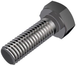
For the parametric bolt modeling the dimensions of the UNI_5739 standard are used as one of the most commonly used in mechanical constructions. (Fig. 3). First it was created a 3D rendered image with the thread visible. (Fig. 1). For the Generic model is is used screw M10x30 mm. All the Configurations are created in Design table, using Solidworks‘abilities to create multiple configurations with an easy way to change, update, and modify.
In Table 1 are shown part of the all-bolt types created for the parametric model with their main parameters, highlighted in Fig. 3 and Fig. 4. In Table 2 all the used bolts are shown with the specific thread and the length it is going to create for the parametric modeling.
UNI-5739-M10-30 (code assign)
UNI - 5739 - Standard
M10 – Type thread
30 – Working length
|
|
|
|
Fig. 1. Rendered image of Bolt 5739 |
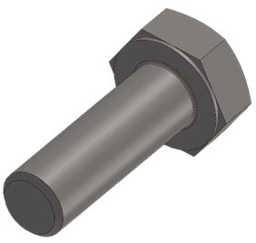
Fig. 2. Working image of Bolt 5739 |
Types of thread used for the parametric model - M3, M4, M5, M6, M8, M10, M12, M14, M16, M18, M20, M22, M24 .
Table 1. Bolt UNI_5739
|
Thread |
Pitch |
k |
s |
L |
Code |
|
M3 |
0.5 |
2 |
5.5 |
6 |
UNI-5739-M3-6 |
|
M3 |
0.5 |
2 |
5.5 |
8 |
UNI-5739-M3-8 |
|
M3 |
0.5 |
2 |
5.5 |
10 |
UNI-5739-M3-10 |
|
M3 |
0.5 |
2 |
5.5 |
12 |
UNI-5739-M3-12 |
|
M3 |
0.5 |
2 |
5.5 |
16 |
UNI-5739-M3-16 |
|
M3 |
0.5 |
2 |
5.5 |
20 |
UNI-5739-M3-20 |
|
M3 |
0.5 |
2 |
5.5 |
25 |
UNI-5739-M3-25 |
|
M3 |
0.5 |
2 |
5.5 |
30 |
UNI-5739-M3-30 |
|
M4 |
0.7 |
2.8 |
7 |
6 |
UNI-5739-M4-6 |
|
M4 |
0.7 |
2.8 |
7 |
8 |
UNI-5739-M4-8 |
|
M4 |
0.7 |
2.8 |
7 |
10 |
UNI-5739-M4-10 |
|
M4 |
0.7 |
2.8 |
7 |
12 |
UNI-5739-M4-12 |
|
M4 |
0.7 |
2.8 |
7 |
16 |
UNI-5739-M4-16 |
|
M4 |
0.7 |
2.8 |
7 |
20 |
UNI-5739-M4-20 |
|
M4 |
0.7 |
2.8 |
7 |
25 |
UNI-5739-M4-25 |
|
M4 |
0.7 |
2.8 |
7 |
30 |
UNI-5739-M4-30 |
|
M4 |
0.7 |
2.8 |
7 |
35 |
UNI-5739-M4-35 |
|
M4 |
0.7 |
2.8 |
7 |
40 |
UNI-5739-M4-40 |
|
M4 |
0.7 |
2.8 |
7 |
45 |
UNI-5739-M4-45 |
|
M4 |
0.7 |
2.8 |
7 |
50 |
UNI-5739-M4-50 |
|
M4 |
0.7 |
2.8 |
7 |
55 |
UNI-5739-M4-55 |
|
M4 |
0.7 |
2.8 |
7 |
60 |
UNI-5739-M4-60 |
|
M4 |
0.7 |
2.8 |
7 |
65 |
UNI-5739-M4-65 |
|
M4 |
0.7 |
2.8 |
7 |
70 |
UNI-5739-M4-70 |

Fig. 3. Drawing of the working parameters of Bolt 5739
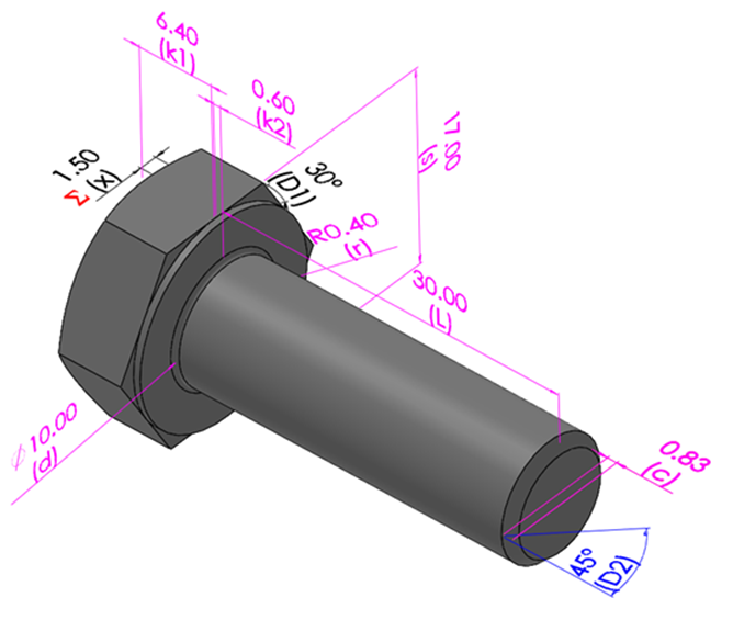
Fig. 4. 3D image of the working parameters of Bolt 5739
Table 2. UNI_5739 with different length range
|
Thread |
Pitch |
k |
s |
L |
Code |
|
M5 |
0.8 |
3.5 |
8 |
(6-80) |
- |
|
M6 |
1 |
4 |
10 |
(6-80) |
- |
|
M8 |
1.25 |
5.5 |
13 |
(8-110) |
- |
|
M10 |
1.5 |
7 |
17 |
(8-150) |
- |
|
M12 |
1.75 |
8 |
19 |
(10-150) |
- |
|
M14 |
2 |
9 |
22 |
(10-150) |
- |
|
M16 |
2 |
10 |
24 |
(12-150) |
- |
|
M18 |
2.5 |
12 |
27 |
(16-200) |
- |
|
M20 |
2.5 |
13 |
30 |
(16-200) |
- |
|
M22 |
2.5 |
14 |
32 |
(20-200) |
- |
|
M24 |
3 |
15 |
36 |
(20-200) |
- |
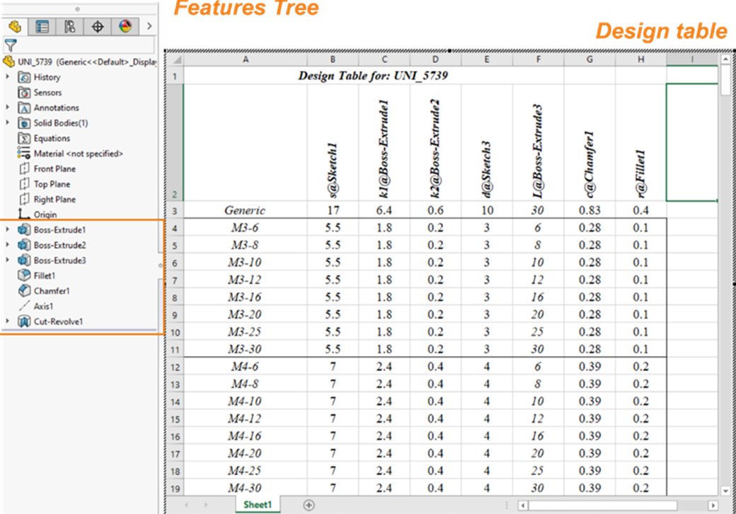
Fig. 5. Feature Tree and Design table
In Fig. 5 is displayed the feature tree of the creation of the parametric bolt with the design table with all the free parameters. From here it can create an infinite number of different designs.
3.1.2 Parametric washer modeling
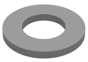
For the plain washer modelling, the UNI_6592 standard is used as one of the most commonly used in mechanical constructions. (Fig. 8). First, a 3D image is created. (Fig. 6). For the Generic model washer M10 is used. All the Configurations are created in Design table, using Solidworks’ abilities to create multiple configurations with easy change, update, and modification. In Fig. 8 are displayed the working parameters used to create the washer.
In Table 3 are shown all different types of washers created for the parametric model with their main parameters, highlighted in Fig. 7 and Fig. 8.
|
|
|
|
Fig. 6. Image of Washer 6592 |
Fig. 7. Working image and parameters of Washer 6592 |
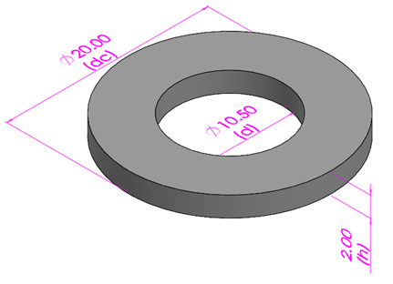
The feature tree is created in a similar manner as the bolt component, with the number of features depending on the complexity of the design. The Design table feature is also used, for which a simplified version is shown in Table 3. All the parameters used for the creating of the model are shown.
The code is generated as followed:
UNI-6592-10 (code assign)
UNI - 6592 - Standard
10 – For type thread
Table 3. Washer UNI_6592
|
Size |
d |
dc |
h |
Code |
|
2 |
2.2 |
5 |
0.3 |
UNI-6592-2 |
|
3 |
3.2 |
7 |
0.5 |
UNI-6592-3 |
|
4 |
4.3 |
9 |
0.8 |
UNI-6592-4 |
|
5 |
5.3 |
10 |
1 |
UNI-6592-5 |
|
6 |
6.4 |
12 |
1.6 |
UNI-6592-6 |
|
8 |
8.4 |
16 |
1.6 |
UNI-6592-8 |
|
10 |
10.5 |
20 |
2 |
UNI-6592-10 |
|
12 |
13 |
24 |
2.5 |
UNI-6592-12 |
|
14 |
15 |
28 |
2.5 |
UNI-6592-14 |
|
16 |
17 |
30 |
3 |
UNI-6592-16 |
|
18 |
19 |
34 |
3 |
UNI-6592-18 |
|
20 |
21 |
37 |
3 |
UNI-6592-20 |
|
22 |
23 |
39 |
3 |
UNI-6592-22 |
|
24 |
25 |
44 |
4 |
UNI-6592-24 |

Fig. 8. Drawing of the working parameters of Washer 6592
3.1.3 Parametric elastic washer modeling
For the parametric modeling of the elastic washer, the dimensions for the UNI_1751 standard are used, for the same reasons listed above. (Fig. 11). First, a 3D rendered image is created with open before mounting design (Fig. 9). For the Generic model an elastic washer 10 is used. Fig.10 shows the closed working design when mounted with the parameters of the model. All the Configurations are created in Design table, using Solidworks’ abilities to create multiple configurations with easy change, update, and modification.
|
|
|
|
Fig. 9. Rendered image of Elastic washer 1751 |
Fig. 10. Working image and parameters of Elastic washer 1751 |
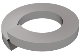
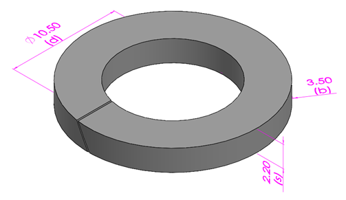
Table 4. Elastic Washer UNI_1751
|
Size |
d |
b |
S |
h |
Code |
|
2 |
2.2 |
0.9 |
0.5 |
1 |
UNI-1751-2 |
|
3 |
3.2 |
1.3 |
0.8 |
1.6 |
UNI-1751-3 |
|
4 |
4.3 |
1.5 |
0.9 |
1.8 |
UNI-1751-4 |
|
5 |
5.3 |
1.8 |
1.2 |
2.4 |
UNI-1751-5 |
|
6 |
6.4 |
2.5 |
1.6 |
3.2 |
UNI-1751-6 |
|
8 |
8.4 |
3 |
2.1 |
4 |
UNI-1751-8 |
|
10 |
10.5 |
3.5 |
2.2 |
4.4 |
UNI-1751-10 |
|
12 |
13 |
4 |
2.5 |
5 |
UNI-1751-12 |
|
14 |
15 |
4.5 |
3 |
6 |
UNI-1751-14 |
|
16 |
17 |
5 |
3.5 |
7 |
UNI-1751-16 |
|
18 |
19 |
5 |
3.5 |
7 |
UNI-1751-18 |
|
20 |
21 |
6 |
4 |
8 |
UNI-1751-20 |
|
22 |
23 |
6 |
4 |
8 |
UNI-1751-22 |
|
24 |
25 |
7 |
5 |
10 |
UNI-1751-24 |

Fig. 11. Drawing of the working parameters of Elastic washer 1751
In Table 4 are shown all different types of washer parameters, created for the parametric model with their main parameters, highlighted in Fig. 10 and Fig. 11.
3.1.4 Parametric nut modelling
For the parametric modeling of the nut, the measure for the UNI_5588 standard is used for the same reasons previously stated. (Fig. 14). Again, a 3D rendered image is created with the thread visible. (Fig. 12). For the Generic model, nut M10 is used. All the Configurations are created with the same logic in Design table.
|
|
|
|
Fig. 12. Rendered image of Nut 5588 |
Fig. 13. Working image and parameters of Nut 5588 |
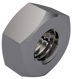
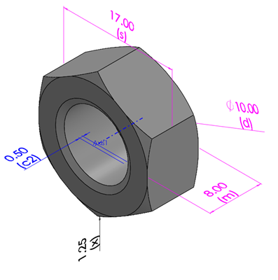
Table 5. Nut UNI_5588
|
Thread |
Pitch |
m |
s |
Code |
|
M3 |
0.5 |
2.4 |
5.5 |
UNI-5588-M3 |
|
M4 |
0.7 |
3.2 |
7 |
UNI-5588-M4 |
|
M5 |
0.8 |
4 |
8 |
UNI-5588-M5 |
|
M6 |
1 |
5 |
10 |
UNI-5588-M6 |
|
M8 |
1.25 |
6.5 |
13 |
UNI-5588-M8 |
|
M10 |
1.5 |
8 |
17 |
UNI-5588-M10 |
|
M12 |
1.75 |
10 |
19 |
UNI-5588-M12 |
|
M14 |
2 |
11 |
22 |
UNI-5588-M14 |
|
M16 |
2 |
13 |
24 |
UNI-5588-M16 |
|
M18 |
2.5 |
15 |
27 |
UNI-5588-M18 |
|
M20 |
2.5 |
16 |
30 |
UNI-5588-M20 |
|
M22 |
2.5 |
18 |
32 |
UNI-5588-M22 |
|
M24 |
3 |
19 |
36 |
UNI-5588-M24 |

Fig. 14. Drawing of the working parameters of Elastic washer 1751
In Table 5 are shown all different types of nuts created for the parametric model with their main parameters, highlighted in Fig. 13 and Fig. 14.
UNI-5588-M10 (code assign)
UNI-5588 - Standard
M10 – For type thread
3.2 Modeling the bolted joint
For the parametric bolted joint an assembly is created (Fig. 15 – render, Fig. 16 – working image) with all the components. For the Generic model a M10 bolted joint is used with the following elements:
- UNI – 5739 - M10 - 30 – 1 pcs;
- UNI – 6592 - 10 – 2 pcs;
- UNI – 1751 - 10 – 1 pcs;
- UNI - 5588 - M10 – 1 pcs.
These elements are creating a bolted assembly with L=12 mm (mounting size).
ASM-M10-12 (code assign)
ASM - Assembly
M10 – For type thread
12 – L – mounting distance
In Table 6 are shown the parametric values, based on the type of thread and the length. This is creating multiple variants for each thread. The important thing here is to be sure that the mounting distance – L - is correct and the threads after the nut are minimum three.
|
|
|
|
Fig. 15. Rendered image of Bolt assemblly |
Fig. 16. Working image and parameters of Bolt assemblly |
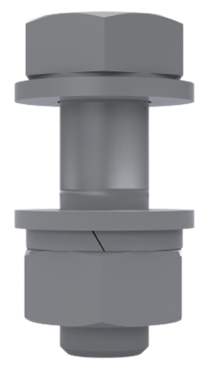
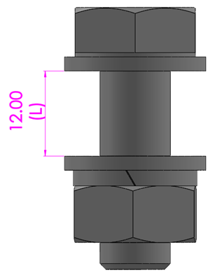
Table 6. Bolt Assembly
|
Thread |
L |
Code |
|
M3 |
(5-20) |
ASM-M3-L |
|
M4 |
(5-20) |
ASM-M4-L |
|
M5 |
(10-40) |
ASM-M5-L |
|
M6 |
(10-40) |
ASM-M6-L |
|
M8 |
(10-40) |
ASM-M8-L |
|
M10 |
(10-40) |
ASM-M10-L |
|
M12 |
(10-40) |
ASM-M12-L |
|
M14 |
(10-40) |
ASM-M14-L |
|
M16 |
(15-50) |
ASM-M16-L |
|
M18 |
(15-50) |
ASM-M18-L |
|
M20 |
(15-50) |
ASM-M20-L |
|
M22 |
(15-50) |
ASM-M22-L |
|
M24 |
(15-50) |
ASM-M24-L |
|
a) |
|
|
b) |
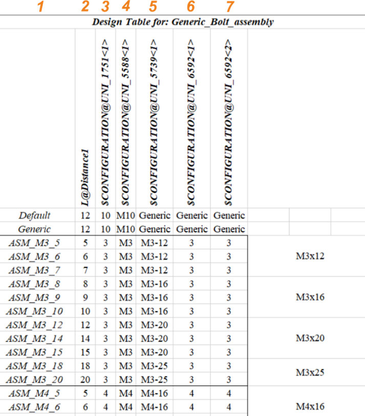
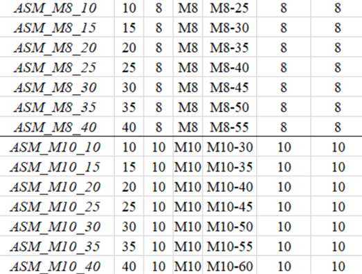
Fig. 17. Samples of bolted joints configuration in the Design table
Fig. 17 shows the Design table, created specifically for the bolted assembly. All the parameters used (components) are shown in the columns: 1 – Code of the bolted assembly; 2 – L – Mounting distance; 3 – Type of Elastic Washer UNI_1751; 4 – Type of Nut UNI_5588; 5 – Type of Bolt UNI_5739; 6 – Type of Washer (Bolt side) UNI_6592; 7 – Type of Washer (Nut side) UNI_6592.
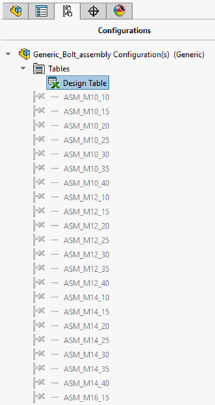
Fig. 18. Working configurations of the bolted joint
Fig. 18 shows (part) of the multiple variants with easy access from the program menu. From here the designer could choose the needed variant of the bolted assembly.
3.3 Samples for using in practice
In Fig. 19 is suggested a sample of metal construction support with several elements. Here the bolted assembly is used to easily apply the needed variant according the mounting length.
In this particular case, two different types of bolted joint are present – ASM-M16-30 and ASM-M20-35. They can be easily chosen and applied from the multiple configurations in Fig. 20. In this sample only two different types of bolted joints are present, but in other cases there can be ten, twenty or more different mounting lengths. With this parametric model the bolted joints can be easily applied, using also the Copy mate’s feature.
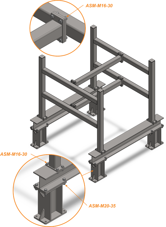
Fig. 19. Metal construction using the bolt assembly model
|
|
|
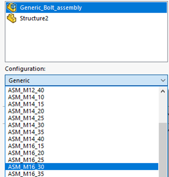
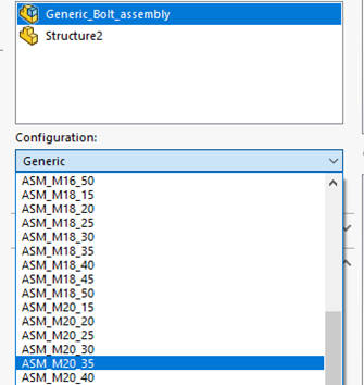
Fig. 20. Different configurations
4 Conclusions
This study demonstrates the effectiveness of parametric modeling in enhancing the design, analysis, and optimization of bolted assemblies within industrial applications. By leveraging CAD-based parametric techniques, engineers can efficiently model complex assemblies, modify geometries dynamically, and analyze various configurations. This significantly reduces the design and needed time for update.
Future work may focus on integrating parametric models for complex metal construction, with easy-to-update and design features, and also focus on integrating parametric models with machine learning algorithms to automate design optimization, as well as incorporating real-time feedback from manufacturing and assembly processes to further refine model accuracy and applicability.
Acknowledgements
The author would like to thank the Research and Development Sector at the Technical University of Sofia for the financial support.
References
- Maggi Y.I., Gonçalves R.M., Leon R.T. and Ribeiro L.F.L. (2005): Parametric analysis of steel bolted end plate connections using finite element modeling. - Journal of Constructional Steel Research, vol. 61, Issue 5, pp. 689-708. https://doi.org/10.1016/j.jcsr.2004.12.001
- Bhonge P., Foster B., Lankarani H. (2011): Finite element modeling and analysis of structural joints using nuts and bolts. - ASME International Mechanical Engineering Congress and Exposition, IMECE2011-62905, pp. 73-83; 11 pages.
- Stocchi C., Robinson P. and Pinho S.T. (2013): A detailed finite element investigation of composite bolted joints with countersunk fasteners - Composites Part A: Applied Science and Manufacturing, vol. 52, pp. 143-150. https://doi.org/10.1016/j.compositesa.2012.09.013
- Sarka, F. (2023). Modelling possibilities of bolt connections with finite element method. Design of Machines and Structures, 13(1). University of Miskolc. https://doi.org/10.32972/dms.2023.009.
- Sun, L., Li, L., Li, J. (2024). Analysis of bolt bonding surfaces by the finite element method based on the equivalent Iwan model. Discover Mechanical Engineering, 3, 41. SpringerLink. https://doi.org/10.1007/s44245 024 00075 2
- Ried J. and Hiser N. (2005) - Detailed modeling of bolted joints with slippage. - Finite Elements in Analysis and Design, vol. 41, pp. 547-562. https://doi.org/10.1016/j.finel.2004.10.001
- Qingyuan L., Yong Z., Yuming L., Wei P., Yu R. and Wencai Y. (2025): Optimization of assembly parameters for composite bolted joints aiming at time-varying bearing reliability improvement - Composite Structures, vol. 363, 119113. https://doi.org/10.1016/j.compstruct.2025.119113
- Liu, H. (2023). A novel bolted joint model with stick slip hysteresis behaviors. Engineering Structures, 293, 116779. ScienceDirect. https://doi.org/10.1016/j.engstruct.2023.116779.
- Haiek, M., El Ansari, Y., Ben Said Amrani, N., Sarsri, D. (2023). Development of a prediction model for the behavior of bolted structure with an elastic part joint based on metamodel approach. Journal of Applied Engineering Science, 21(1). https://doi.org/10.5937/jaes0-40064
- Wall M., Allen M. and Kuether R. (2022): Observations of modal coupling due to bolted joints in an experimental benchmark structure - Mechanical Systems and Signal Processing, vol. 162, 107968. https://doi.org/10.1016/j.ymssp.2021.107968
- Daniel R. and Matthew A. (2017): Nonlinear characterization of a bolted, industrial structure using a modal framework - Mechanical Systems and Signal Processing, vol. 84, Part B, pp. 152-170. https://doi.org/10.1016/j.ymssp.2015.11.010
- Dimitrova, V. K. (2025). Microstructural evolution and mechanical properties of cold‑drawn 1566 steel wire subjected to heat treatment recrystallization annealing. International Journal of Mechatronics and Applied Mechanics (IJOMAM), 1(20), 95–102. https://doi.org/10.17683/ijomam/issue20.9.
- Dimitrov, V., Dimitrova, V. K., Zdravcheva, G. S. (2025). Investigation and optimization of process parameters for electrochemical rifling of firearm barrels. International Journal of Mechatronics and Applied Mechanics (IJOMAM), 1(21), 40–48. https://doi.org/10.17683/ijomam/issue21.4
- Tomova‑Damyanova, E., Ivanov, V., Tonkov, G., Tsonev, V., Kuzmanov, N. (2024). Shape‑Memory Alloys—Application in Shrink‑Fit Joints. Engineering Proceedings, 70(1), 10. https://doi.org/10.3390/engproc2024070010
- Renhong W., Xiuli W., Zhihua C. and Baolong G. (2025) - Test and parametric analysis of steel-aluminum alloy composite bolted joint – Structures, vol. 74, 108501. https://doi.org/10.1016/j.istruc.2025.108501
- Ma, Y., Fu, Y., Tian, Y., Liu, X. (2023). Semi analytical stiffness model of bolted joints in machine tools considering the coupling effect. Nanomanufacturing and Metrology, 6(1), Article 17. SpringerLink. https://doi.org/10.1007/s41871 023 00195 5
- Liu, Y. (2024). Simulation of preload relaxation of bolted joint structures under transverse loads. Coatings, 14(5), 538. MDPI. https://doi.org/10.3390/coatings14050538
- Yang, M., Jeong, S.-M., Lim, J. Y. (2023). A phenomenological model for bolt loosening characteristics in bolted joints under cyclic loading. International Journal of Precision Engineering and Manufacturing, 24(8), 1601–1610. https://doi.org/10.1007/s12541-023-00783-x
- Goteti V. (2003): Parametric modeling of bolted joints between components made of particulate composite materials. - West Virginia University, Mechanical and Aerospace Engineering, Thesis.
- Boujnah I., Afifi N., Wettstein A. and Matthiesen S. (2024): Towards Precision in Bolted Joint Design: A Preliminary Machine Learning - ICED25 - 25th International Conference on Engineering Design.
- Petrov N., Dimitrov V., Dimitrova V. (2024): Reliability assessment of electromechanical module with association among reliability indicators. - Applied Engineering Letters, vol. 9, Issue 2, Pages 85 - 93.
- Zhang S., Devriendt H., Belle L.V. and Desmet W. (2024): Substructuring-based parametric reduced-order modelling for structural dynamic predictions of bolted assemblies. - Mechanical Systems and Signal Processing, vol. 218, article number 111513. https://doi.org/10.1016/j.ymssp.2024.111513
- Li Y., Zhu Z., Wen C., Luo Z. and Long T. (2024): Dynamic modelling and parametric analysis of a bolted joint rotor-bearing system considering stick-slip behavior at mating interface. - International Journal of Non-Linear Mechanics, vol. 159, 104631. https://doi.org/10.1016/j.ijnonlinmec.2023.104631
Conflict of Interest Statement
The author declares that there are no conflicts of interest regarding the publication of this paper. The research was conducted independently, with no personal relationships with other people that could have influenced the work reported in this paper.
Author Contributions
Data Availability Statement
No dataset is associated with this study.
Supplementary Materials
There are no supplementary materials to include.