Volume 23 number 3 article 1285 pages 437-455
Received: Jan 13, 2025 Accepted: Jul 18, 2025 Available Online: Sep 10, 2025 Published: Sep 15, 2025
DOI: 10.5937/jaes0-55983
PERFORMANCE OF CONCRETE SLABS WITH WASTE MATERIALS: A STUDY USING FINITE ELEMENT ANALYSIS
Abstract
This study investigates the structural behavior of green concrete slabs incorporating waste materials under load conditions using finite element analysis (FEA), aligning with the principles of sustainable construction and responsible consumption and production. The objective is to enhance the mechanical properties of green concrete while reducing carbon dioxide (CO₂) emissions by minimizing cement consumption. Various waste materials, including coconut shells, waste tires, mining byproducts, wastewater treatment sludge, and coastal shells, are evaluated for their potential to improve concrete durability and support circular economy practices. Finite element simulations conducted using Abaqus assess the mechanical performance of these modified concrete slabs. The results indicate significant variations in structural behavior depending on composition. Based on experimental testing and finite element modeling, water treatment sludge concrete (WTSC) exhibited the highest stress response at 0.1016 MPa, while crumb rubber concrete (CRC) recorded the lowest at 0.06044 MPa. Incorporating 3.5% oyster shell waste reduced compressive strength from 36.20 N/mm² to 30.80 N/mm², whereas adding 3.0% coconut fiber reinforcement (CFRC) increased compressive strength to 37.30 N/mm². Among the tested formulations, CRC demonstrated the greatest resistance to external forces in the X, Y, and Z directions. These findings highlight the potential of waste-based concrete mixtures to enhance structural integrity while promoting environmental sustainability. This study reinforces the feasibility of integrating waste materials into concrete as a viable alternative for eco-friendly and climate-resilient infrastructure.
Highlights
- This study investigates concrete slabs modified with waste materials (coconut fibers, crumb rubber, mining residues, oyster shells, and water treatment sludge) using finite element analysis and laboratory testing.
- The results show that different waste additions significantly influence mechanical behavior: WTSC achieved the highest compressive and flexural strength, while CRC provided improved ductility and energy absorption.
- Incorporating waste materials supports sustainable construction by reducing cement consumption, lowering CO₂ emissions, and promoting circular economy practices.
- The combined use of experiments and Abaqus simulations confirms the feasibility of green concrete for eco-friendly and climate-resilient infrastructure applications.
Keywords
Content
1 Introduction
Over the past four decades, the world economy has grown so fast that immense infrastructure construction [1] milestones have been achieved within this period. The result of such growth was that so many high-rise buildings were constructed that the global consumption of concrete reached almost 3 billion tons per year. With cement as one of the most important ingredients of concrete, it consumes 5-7% of global CO2, and each tonne of cement produces a tonne of CO2 [2]. These have been implicated in global warming, rising sea levels, among other environmental problems [3].
With the rising concern for environmental issues in producing concrete, industrial waste and natural materials are being tried as substitutes for some of the conventional ingredients in concreting [4]. Such materials include natural resources coconut shells, oyster shells, and even bamboo [5]. SPs improve the geopolymer and alkali-activated concretes upon their use in desired dosages; more dosage leads to negative effects [6]. The optimization of use date palm ash (DPA) and eggshell powder (ESP) showed that the blending 14.77 % DPA and 2.2 % ESP gave the best performance in the concrete properties with desirability of 91.1 % [7] and significantly reduced embodied CO2 emissions and cost, enhanced eco-strength efficiency of the concrete [8].
Recent studies have explored the partial replacement of cementitious materials with recycled aggregates to address challenges in construction. For instance, Qaidi and his team [9] demonstrated that substituting 30% natural coarse aggregates with waste rubber can maintain compressive strength while reducing cement content by 15-18%. Include the incorporation of rubber particles (1-4 mm) as fine aggregate replacement. Ahmad et al. [10] found that by optimizing particle packing density, cement was reduced by 22%* while diverting 2.1 kg/m3 of tire waste from landfill.
Conventional concrete, though widely used for strength and durability, has certain limitations due to tensile strength and crack resistance under variable conditions [11]. Due to low tensile strength and shrinkage, traditional concrete is liable to crack during the process of hardening [12]. Due to such disadvantages, it may allow moisture and harmful substances to penetrate and thus compromise durability and safety.
Different performances may be performed by changing different proportions of coconut fibers to the interfacial bonding strength between the fiber and concrete matrix. The long-term durability of coconut fibers in concrete [13], which is resistant to alkalinity and corrosion, also remains a point of concern. In-depth research into the long-term performance of coconut fibers in concrete in different environmental conditions is required to ascertain its reliability for practical applications [14]. The incorrect proportioning may result in lower strength than expected from concrete [15], which makes the composite strength lower than that of ordinary concrete. Certain composite materials are not compatible with the required strength. Further experimental studies, accumulations of data, establishment of appropriate predictive models, and design guidelines are urgently needed.
This study aims to compares five types of waste-modified concrete (rubber particles, calcined water sludge, blast furnace slag, alkali-treated coconut fibers, and oyster shell powder) and reference concrete (C35), addressing the research gap in understanding the differential effects of heterogeneous waste resources in concrete. Five independent multi-scale models were developed using Abaqus: rubber concrete (10% fine aggregate replacement, 1-4 mm particle size), water sludge concrete (30% calcined sludge replacing sand), slag concrete (40% cement replacement), coconut fiber concrete (0.5 vol% alkali-treated fibers), and shell concrete (50% shell powder replacing fine aggregate). Analysis the pros and cons of each combination, possibly informing future methods for optimization.
The reuse of waste in concrete is one important strategy. Such methodology also contributes to the reduction of environmental impacts and is considered responsible and robust building concerning PoE [16]. This paper intends to discuss how environmental impacts can be reduced by the incorporation of waste materials in concrete mixtures, focusing on the analysis of how such waste materials as wastewater, CFRC, CRC, WTSC, MC, and OSWC are integrated in the production of concrete.
2 Materials and methods
2.1 Materials
2.1.1 Waste tires
Incorporating rubber materials into concrete mixtures significantly enhances its impact resistance. The superior energy absorption capacity of rubber contributes to the improvement of tensile strength and flexural performance in the modified concrete. The research has been done from previous research shown in Table 1 that the use of waste tires in concrete has a wide range of applications in earthquake-resistant buildings, pavements, crash barriers, amusement facilities, and collision protection structures.
Table1. Reinforcement characteristics and influencing factors of rubber concrete
|
Author |
Year |
Materials |
Advance |
Influence Factor |
|
[17] |
2017 |
Rubberized Concrete |
Increased tensile capacity and bending endurance |
Enhanced energy absorption and impact resistance |
|
[18] |
2019 |
FRRC (Fiber-Reinforced Rubberized Concrete) |
Improved flexibility, toughness, impact resistance |
Applications in earthquake-resistant buildings, pavements, barriers |
|
[19] |
2020 |
Rubberized Concrete |
Marked strength increase under compression |
Structural durability under compressive loads |
|
[20] |
2018 |
Rubberized Concrete |
Environmental sustainability (recycled tires) |
Reduced energy consumption, resource conservation |
However, concrete modified with rubber waste also faces some challenges and limitations in its use. Adding rubber particles to concrete reduces its compressive strength, especially when a high percentage of natural aggregates are replaced. The results regarding long-term durability are mixed, including potential issues with the bonding between the rubber particles and the cement matrix, which may affect water absorption and freeze.
2.1.2 Water treatment sludge (WTS)
Incorporating industrial waste materials such as sludge from factory wastewater, coal residues, bottom coal ash, and water treatment sludge (WTS) into construction materials can yield eco-friendly products. For instance, using these waste-based materials, eco-friendly concrete paving blocks with a compressive strength of approximately 36 MPa have been produced, meeting Hong Kong's paving standards. Additionally, replacing traditional sand with coal bottom ash in concrete mixtures can enhance compressive strength due to its pozzolanic activity, which improves chemical reactions within the concrete mix the research has been done from previous research shown in Table 2. WTS has also been utilized in producing ceramics, clay bricks, and concrete; substituting 5% of cement or sand with WTS generally maintains material strength. Key geotechnical properties of WTS such as liquid limit, plastic limit, plasticity index, specific gravity, and loss on ignition are essential for assessing its workability, stability, and organic content, thereby supporting its effective application in sustainable construction materials.
Table 2 Reinforcement characteristics and application of sewage sludge concrete
|
Author |
Year |
Materials |
Key Findings |
Applications/Properties |
|
[21] |
2018 |
Sewage sludge, coal residues |
Paving blocks achieve 36 MPa compressive strength |
Compliant with Hong Kong paving standards |
|
[22] |
2023 |
Coal bottom ash (CBA) |
CBA (Coal Bottom Ash)-sand replacement enhances concrete compressive strength |
Pozzolanic activity improves cementitious reactions |
|
[23] |
2022 |
Coal bottom ash (CBA) |
CBA’s pozzolanic reactivity drives chemical interaction in concrete |
Optimized strength development in CBA-concrete |
|
[24] |
2019 |
Water treatment sludge (WTS) |
5% of WTS substitution in cement/sand maintains strength |
Suitable for ceramics, clay bricks, concrete |
|
[25] |
2023 |
Water treatment sludge (WTS) |
LL (Liquid Limit), PL (Plastic Limit) define workability, stability, and organic content |
Critical parameters for WTS-based material design |
But the fact is that WTS has variations in its physical and chemical makeup, plus the organic content it may carry, might introduce certain challenges that could impact the strength and performance of the concrete. Data specific to this can be found in Table 3. It is advised to shine at temperatures exceeding 1000°C to ensure that heavy metals in the WTS-modified product are fully immobilized, to prevent environmental risks.
Table 3. Main geotechnical properties of WTS [26][27][28]
|
Property |
Unit |
Alum sludge |
Ferric sludge |
Lime sludge |
|
Liquid limit |
% |
80-550 |
108 |
38-72 |
|
Plastic limit |
% |
60-325 |
47 |
32-53 |
|
Plasticity index |
% |
20-225 |
61 |
4-19 |
|
Specific gravity |
g/cm3 |
1.86-2.33 |
2.26-2.72 |
2.57-2.62 |
|
Solid classification (USCS) |
|
High-plasticity clay |
High-plasticity clay |
Low-plasticity clay |
|
Loss on ignition |
% |
15-57 |
24-50 |
35-40 |
2.1.3 Mining waste material
Adding slag to concrete mixes significantly affects both the workability and strength of cementitious sand. On one hand, compared with conventional concrete mixes without slag, the addition of slag increases fluidity and prolongs setting time, thereby enhancing construction workability and potentially improving final compressive strength through a controlled heat release during curing [26]. On the other hand, high dosages, blast furnace slag has decrease early compressive strength compared to ordinary Portland cement concrete, mainly by altering initial setting behavior [27]. Moreover, incorporating fly ash or mineral powder in slag concrete (compared to mixes without these additives) improves seepage resistance via secondary hydration that densifies the material [28]. An optimal biochar-slag binder mixture (0.67:0.33 ratio at 10% dosage, compared to traditional cement binders) has also been identified in previous studies (see Table 4), offering promising benefits for soil stabilization, partial cement replacement, and carbon footprint reduction, thus supporting circular economy goals and sustainable construction practices [29].
Table 4. Reinforcement characteristics and application of slag concrete
|
Author |
Year |
Materials |
Advance |
Influence Factor |
|
[29] |
2020 |
Slag in cementitious sand |
Increased fluidity and extended setting time improve workability and final strength |
Enhanced flow and controlled heat release during curing |
|
[30] |
2021 |
Blast furnace slag in concrete |
High slag content reduces early compressive strength |
Alters workability and setting time, affecting initial strength |
|
[31] |
2021/2020 |
Fly ash and mineral powder admixtures in slag concrete |
Improved seepage resistance and impermeability |
Secondary hydration densifies concrete, enhancing water resistance |
|
[32] |
2017 |
Biochar-slag binder |
Optimal mixture for soil stabilization and cement replacement |
Reduces carbon footprint and supports a circular economy, promoting sustainable construction practices aligned with EU strategy |
Due to the hydration of the cement, a significant quantity of heat is generated while the concrete hardens. Because of its great thermal resistance, concrete cannot quickly transfer heat into the surrounding air [33]. Because of the temperature difference between inside and outside the building, heat can build up in the concrete structure. This leads to uneven temperature changes and strains. The buildup of these pressures can cause the concrete to crack early, starting with small microcracks that can grow into larger cracks [34]
2.2 Incorporating coconut fibers
Incorporating coconut fibers can influence the compressive strength of concrete, mainly through improvements in the fiber-matrix interface [35]. However, the enhancement in compressive strength is not always significant and largely depends on the fiber content, distribution, and mix design [36]. Some studies report slight increases in compressive strength, while others observe little or no improvement. Excessive incorporation may trigger microcracks under high loads. In addition, coconut fibers are more notable for improving toughness, impact resistance, and crack resistance, thus offering a sustainable reinforcement option with reduced environmental impact [37].
Table 5. Strengthening properties and application of coconut shell concrete
|
Author |
Year |
Materials |
Key Findings |
Applications/Properties |
|
[35] |
2020 |
Coconut fibers |
Enhanced compressive strength via fiber-matrix bonding; microcracks under high load |
Crack resistance improvement in high-stress environments |
|
[36] |
2015 |
Kenaf fiber (KF), RCA |
0.2% KF ↑ fck by 12%; 0.5% KF ↑ ft by 60%; RCA ↓ fck (30-33%) and ft (13-18%) |
Trade-offs between fiber dosage and RCA utilization in CFRC |
|
[37] |
2021 |
Coconut fibers |
CFRC offers high toughness, impact resistance, and shrinkage crack reduction |
Sustainable applications: walkways, roads; biodegradable, low environmental impact |
2.2.1 Shell waste
Oyster shell waste concrete (OSWC) matches sand-based concrete in tensile strength, with effective cement bonding [38] [39]. OSWC replaces sand sustainably [40], requires minimal processing [41], and reduces landfill waste, and costs, aligning with circular economic goals. The research has been done from previous research shown in Table 6.
Table 6. Reinforcement characteristics and applications of shell concrete
|
Author |
Year |
Materials |
Key Findings |
Applications/Properties |
|
[38] |
2022 |
OSWC |
No significant difference in tensile splitting strength vs. sand-based concrete |
Matrix strength dominates; OSWC-cement bonding mimics natural aggregates |
|
[39] |
2019 |
OSWC |
Smooth shell surfaces do not compromise cement-aggregate interface |
Validates mechanical compatibility between OSWC and cement matrix |
|
[40] |
2018 |
OSWC |
OSWC replaces sand without degrading tensile strength or adhesion |
Sustainable sand alternative for structural and non-structural concrete |
|
[41] |
2024 |
Crushed OSWC |
Simple cleaning processes enable OSWC as fine aggregate |
Low-energy, scalable production for eco-friendly concrete |
2.3 Methods and casting
This study employed a multi-stage numerical analysis approach using the Abaqus finite element software. The process began with a pre-processing stage, where the geometry and material specifications were defined shown in Fig. 1. In this stage, appropriate finite element models were selected, the mesh was generated, and boundary and loading conditions were established. Finite element models of green concrete slabs were developed using 3D solid elements in Abaqus. Mesh refinement was applied particularly in regions expected to experience high stress concentrations to improve result accuracy. Material properties such as density, elastic modulus, and Poisson’s ratio were assigned based on laboratory test data.
To capture the nonlinear behaviour of concrete under load, the Concrete Damage Plasticity model was utilized. Boundary conditions involved fixing the slab at the base, while a uniform load was applied to the top surface to simulate realistic service loading. Surface-to-surface contact interactions were defined, with friction coefficients obtained from relevant literature. Mesh convergence studies were conducted to ensure the numerical stability and accuracy of the simulation results. The simulation outputs, including load-displacement responses and stress distributions, were then validated against experimental data to confirm the model's reliability.
2.3.1 Conceptual Modeling
Designing an Abaqus model involves several steps, from creating geometry to defining material properties, meshing, applying boundary conditions, and setting up the analysis.
2.3.2 Pre-processing
In the pre-processing stage, the specimens—CFRC, CRC, MC, OSWC, WTSC—were modeled in ABAQUS using eight-node reduced integration 3D solid elements (C3D8R), as shown in Fig. 2. The mesh size was determined through mesh sensitivity analysis, ensuring result accuracy with reasonable computational cost. An element size of 30 mm (referring to the edge length) was adopted for both the steel tube and concrete core, with local refinement at the steel-concrete interface, corners, and stress-concentrated areas. The mesh quality was controlled with an aspect ratio close to 1 and skewness below 0.3. Material properties were defined based on experimental data, using an elastic–plastic model for steel (Von Mises yield criterion) and the Concrete Damage Plasticity (CDP) model for concrete. Initial stress, based on measured residual stress, was applied via Predefined Field in ABAQUS and quantified as 𝜎₀/𝜎y = 0.2, meaning 20% of the steel yield stress was preset before loading. Boundary conditions fixed the bottom of the tube, applied axial displacement at the top, and constrained horizontal movement. The steel-concrete interface used Coulomb friction contact with a coefficient of 0.3. The simulation employed a global residual convergence criterion of 10−3.
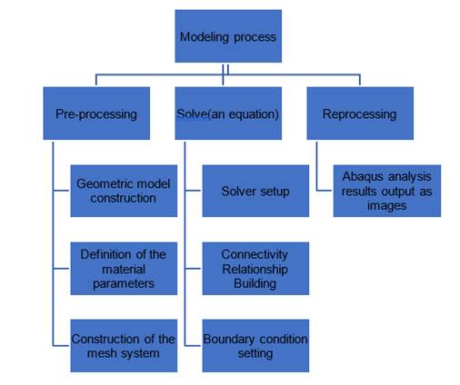
Fig.1. Modeling process of Abaqus
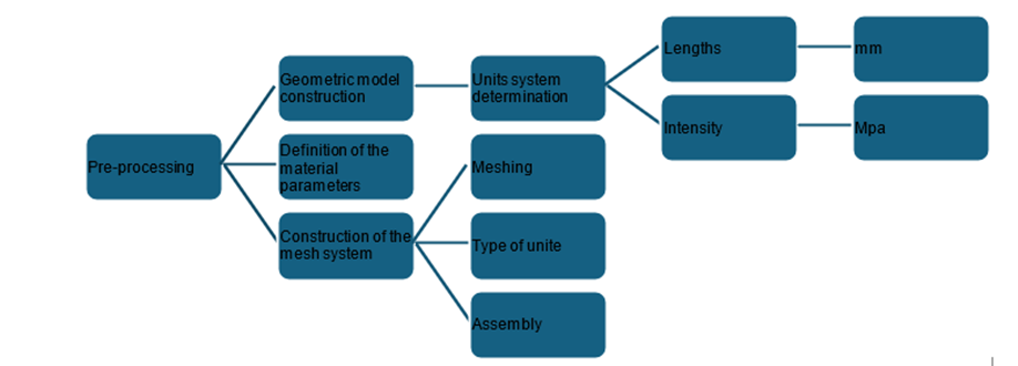
Fig. 2. The process of pre-treatment with Abaqus
2.3.3 Solve the equation
Obtain values such as displacement, stress, strain, and similar metrics from the generated outcomes of the simulations, and from Abaqus, produce various graphical outputs like stress and strain visuals, plus other graphics. This lets one look at how the model acts in various circumstances. By seeing these graphics side-by-side and examining all data, potential design concerns are highlighted, plus theoretical assumptions could also find some level of confirmation.
2.3.4 Test setup
The experimental program utilized standardized specimens (prismatic beams: 100×100×400 mm; cubes: 150×150×150 mm) fabricated in compliance with ASTM C192/C192M. Flexural and compressive strength testing was conducted following ASTM C78 and ASTM C39 respectively. The concrete formulation targeted strength class C35 (characteristic cylinder/cube strength of 35 MPa at 28 days per EN 206-1), employing a mass-based cement: fine aggregate: coarse aggregate ratio of 1:1:2 with a controlled water-cement ratio (w/c) of 0.45. All specimens underwent moist curing at 20±2°C with ≥95% RH (ASTM C511) until testing. The details shown in table 7-8.
Table 7. Quantified Mix Design (ASTM/EN Framework)
|
Component |
Dosage (kg/m³) |
Technical Specifications |
Compliance Standard |
|
Cement |
420 |
Type I Portland cement |
ASTM C150 |
|
Water |
189 |
Mixing water, chloride<500 ppm |
ASTM C1602 |
|
Fine Aggregate |
650 |
Natural sand, FM=2.6, SSD condition |
ASTM C33 |
|
Coarse Aggregate |
1300 |
Recycled concrete aggregate (RCA), 19mm NMS |
EN 12620 |
|
Superplasticizer |
4.2 |
Polycarboxylate ether (PCE), Type F |
ASTM C494 |
|
Fresh Concrete |
2459 |
Slump: 160±20mm, air content 2.1% |
ASTM C143/EN 12350-2 |
Table 8. Standardized Testing Protocol
|
Parameter |
Specification |
Compliance Standard |
|
Curing Regime |
20±2°C, RH≥95% (28-day) |
ASTM C511/EN 12390-2 |
|
Flexural Test Rate |
0.5 MPa/s ±10% |
ASTM C78 |
|
Strength Evaluation |
5% fractile characteristic value |
EN 1992-1-1 |
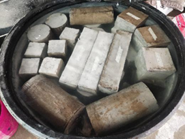
This section conducted Flexural Strength tests and was carried out in lab. The dimensions of the cast-in-place columns are shown in Fig 3.
|
|
|
|
|
|
|
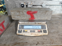
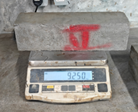
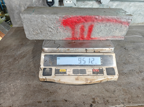
Fig. 3. Test sample
|
|
|
|
|
|
|
|
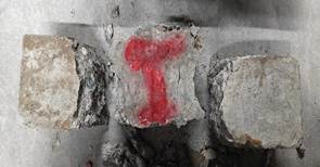
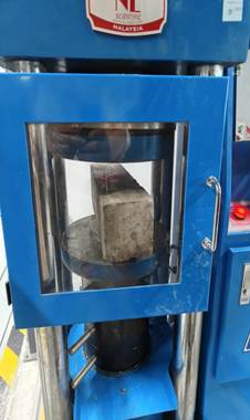
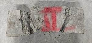
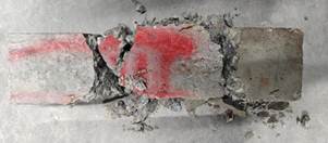
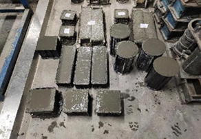
Fig. 4. Flexural Strength Test
The flexural strength test obtained the mechanical properties data of ordinary C35 concrete through laboratory experiments shown in Fig. 4, which serve as a reference for the control group. This provides a reliable foundation for our subsequent modeling and comparative analysis.
The beam specimens were cracked at the middle third of the span at the cross-sectional level and were calculated using the concrete bending strength equation (1) in accordance with ASTM C78: Standard Test Method for Bending Strength of Concrete (Using Simple Beam with Third-Point Loading).
![]() (1)
(1)
Where: 𝜎 is the modulus of rupture, P is the maximum load indicated by the test machine; L is span length, b is the average width of the specimen, d is the average depth of the specimen.
The average compressive strength was determined through laboratory tests, with each type of waste material tested at varying content levels, as shown in Table 9.
Table 9. The Average Compressive strength of different waste materials used
|
Type of waste materials |
The Average Compressive Strength Curing period 28+7 days |
|||
|
Control strength (N/mm2) |
Waste materials content (%) |
Compressive strength (N/mm2) |
Difference (%) |
|
|
C35-CFRC |
36.20 |
2.5 |
37.15 |
2.62 |
|
3.0 |
37.30 |
3.03 |
||
|
3.5 |
36.50 |
0.83 |
||
|
C35-CRC |
2.5 |
40.00 |
10.49 |
|
|
3.0 |
45.50 |
25.69 |
||
|
3.5 |
44.10 |
21.82 |
||
|
C35-MC |
2.5 |
35.40 |
-2.21 |
|
|
3.0 |
36.30 |
0.27 |
||
|
3.5 |
36.00 |
-0.55 |
||
|
C35-OSWC |
2.5 |
32.00 |
-11.60 |
|
|
3.0 |
31.60 |
-12.71 |
||
|
3.5 |
30.80 |
-14.92 |
||
|
C35-WTSC |
2.5 |
35.25 |
-2.62 |
|
|
3.0 |
45.85 |
26.65 |
||
|
3.5 |
33.17 |
-8.37 |
||
Each test was conducted with three samples per waste material content to ensure accuracy and reliability. A noticeable drop in strength was observed in OSWC, decreasing from 32 N/mm² to 30.80 N/mm² when 3.5% waste material was added. In contrast, CFRC exhibited the highest strength gain, increasing from 37.15 N/mm² at 2.5 % to 37.30 N/mm² at 3.0 % CFRC content. This improvement is attributed to the formation of a continuous polymer network that enhances bending capacity, rather than relying solely on cement hydration or mortar strength. Although laboratory experiments offer precise results, they require long durations to complete, whereas numerical modeling can simulate multiple conditions in a short time.
Figure 5 compares laboratory test results with corresponding numerical/computational model predictions, demonstrating good agreement. Based on this validation, the model was then employed to explore additional design parameters and conditions efficiently, thereby optimizing resource utilization.
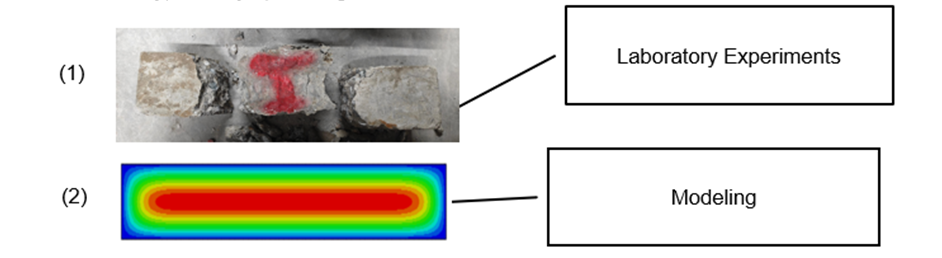
Fig. 5. Comparison of laboratory experiments and modeling (example)
1.1.1 Geometry modeling
The model parameters are units in millimeters (mm) for length and megapascals (MPa) for strength to ensure consistency and accuracy. The model framework is a three-dimensional solid with extrusion dimensions of 3600 mm * 500 mm * 120 mm shown in Fig. 6.
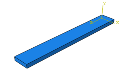
Fig. 6. Geometry modeling
The material properties listed in Table 10, including Young’s modulus, shear modulus, Poisson’s ratio, and density, were entirely sourced from published literature. In particular, the shear modulus was calculated using the standard relation G = E / [2(1 + ν)] based on the reported Young’s modulus and Poisson’s ratio values. These parameters are essential for finite element modeling and analysis in ABAQUS, as they directly govern the material behavior under various loading conditions and significantly influence the accuracy of the simulation results.
Table 10. Material properties
|
Material |
CFRC |
CRC |
mc |
OSWC |
WTSC |
|
YOUNG’S modulus (MPa) |
41200 |
48900 |
43010 |
32630 |
25200 |
|
Shear Modulus (MPa) |
3180 |
3550 |
3570 |
2510 |
3120 |
|
Poisson's ratio |
0.26 |
0.35 |
0.127 |
0.25 |
0.26 |
|
Density kg/m³) |
2930 |
2180 |
3160 |
1820 |
3020 |
|
Reference |
[26] [37] |
[38] [39] |
[43] [44] |
[42] [43] |
[44] |
Young's modulus is defined as the ratio of the stress (force per unit area) applied to the object and the resulting axial strain (displacement or deformation) in the linear elastic region of the material.
In Mesh Controls, a type of mesh is set to be hexahedral in shape, with a size across the whole mesh set broadly at around 30, along with the use of smaller local divisions that focus more on the vertical sides, dividing them into about 6 parts. The elements are labeled as C3D8R. Various parts or components are set up carefully, making sure each is placed in its correct location, with contacts, boundary constraints, and any other conditions properly arranged for them. A discrete rigid component is also assigned as part of the model, and material details are included from within the Assembly section.
The analysis approach uses a static general method, which considers linear geometry. The outputs that are examined involve RF1, RF2, RF3, RT, CF2, as well as TF2. Inside the Assembly section, the rigid entity made discrete is selected to connect with the model. Geometry sides, all four of them, are fixed fully along each side’s four planes. To make the geometry simpler for calculating and to reduce the complexity in loads across various points or planes, which could lessen both calculation difficulty and required time, boundary settings get applied to RP-1. Full constraints are set on RP-1, with U1, U2, U3, UR1, UR2, and UR3 all fully restricted, and an added gravity load specified broadly as 9800 along with a pressure set at 2000*e-6 covering evenly the plane facing toward RP-1. Fig. 7 could provide additional visualization for these.
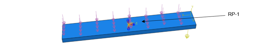
Fig. 7. Assembly and load
3 Result and discussion
Numerical simulations in ABAQUS were carried out to investigate the quasi-static axial compression behavior of five types of waste-modified concrete slabs: coconut fiber-reinforced concrete (CFRC), crumb rubber concrete (CRC), mining waste concrete (MC), oyster shell waste concrete (OSWC), and water treatment sludge concrete (WTSC). The finite element model treated each slab as plain concrete (with no steel tube reinforcement), ensuring the focus remained on the concrete’s performance alone. Each slab’s material properties (elastic modulus, Poisson’s ratio, density) were defined from experimental mix data. The slab base was fully fixed and a quasi-static axial compressive load was applied at the top, to evaluate the compressive response of each modified concrete slab under longitudinal compression.
3.1 Load displacement curve analysis
The numerical analysis was conducted based on the detailed finite element model described in Section 3.2 Pre-processing, where all modeling parameters and procedures, including element type, mesh settings, material models, initial stress application (𝜎₀/𝜎y = 0.2), and boundary conditions, were clearly defined. Poisson’s ratios and load-displacement data were extracted from simulated strain and reaction force outputs. The following analysis is based on these simulation results.
In longitudinal compression, concrete slabs experience lengthwise compression, resulting in bending effects that mainly impact the central slab area. This central bending stress can lead to cracking or larger fractures, particularly in the slab's center. Concrete is strong under compression but weaker under tension, so unevenly distributed compressive loads may cause localized cracking, potentially leading to structural failure.
Changes in Damage Patterns: At low loads, minor surface cracks or warping may appear; under higher loads, significant bending, potential compression, and large cracks can occur. This reflects the non-linear nature of stress behavior, complicating strain prediction.
|
|
|
|
C35-CFRC(a) |
C35-CRC(b) |
|
|
|
|
C35-MC(c) |
C35-OSWC(d) |
|
C35-WTSC(e) |
|
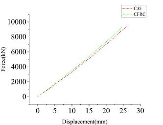
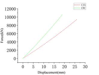
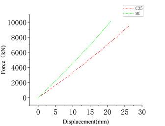
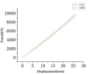
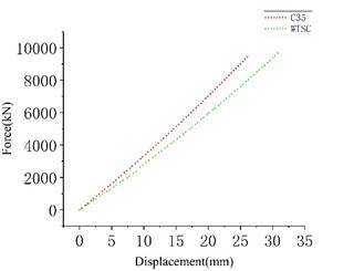
Fig. 8. Load displacement curve
The linear equations of the load-displacement curves for C35, CFRC, CRC, MC, OSWC, and WTSC can be obtained from Figure 8.
![]() (5)
(5)
![]() (6)
(6)
![]() (8)
(8)
![]() (9)
(9)
![]() (10)
(10)
![]() (11)
(11)
![]() (12)
(12)
![]() (13)
(13)
![]() (14)
(14)
![]() (15)
(15)
![]() (16)
(16)
Where:
- y is the applied force (kN)
- x is the displacement (mm)
- The slope represents stiffness (kN/mm)
- The R2 value indicates the goodness of fit of the linear model
The linear equations representing the load-displacement behavior of C35, CFRC, CRC, MC, OSWC, and WTSC can be obtained from Figure 8. These equations describe how each concrete type responds to applied force in terms of displacement and can be used to compare stiffness and overall mechanical performance. The slope of each equation reflects stiffness (kN/mm), while the y-intercept indicates the theoretical force offset. Among the tested materials, CRC exhibits the highest stiffness with a slope of 569.19 (Equation 7), followed by MC at 492.32 (Equation 8), indicating their superior resistance to deformation underload. CFRC, OSWC, and C35 show similar stiffness values with slopes of 386.52 (Equation 6), 387.02 (Equation 9), and 372.67 (Equation 5), respectively. WTSC has the lowest stiffness, with a slope of 325.17 (Equation 10), suggesting more flexible behavior. The coefficients of determination (R2) for all models range between 0.991 and 0.999, with the highest being for C35 (R2=0.999, Equation 11) and the lowest for CFRC and OSWC (R2=0.991, Equations 12 and 15). These high R2 values confirm that the linear models fit the experimental data very well, ensuring consistency and reliability of the test results. Despite the presence of negative y-intercepts in the equations, these are considered mathematical artifacts due to extrapolation and do not represent actual physical force at zero displacement.
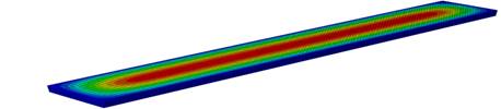
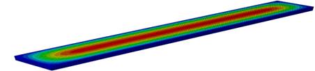
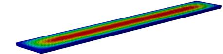
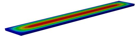
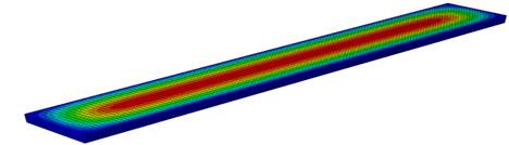
The stress distribution profiles further support these observations. As detailed in Table 11, the WTSC configuration reaches a peak stress of approximately 0.1016 MPa, while the CRC scheme exhibits the lowest peak stress at around 0.06044 MPa. Stress concentrations are consistently found near profile bends and interface connections, highlighting areas that may require targeted reinforcement. Additionally, Table 12 presents equivalent strain values ranging from about 2.18e-04 m (MC) to 3.72e-04 m (WTSC). Generally uniform strain distribution suggests effective load sharing throughout the structure, reducing the risk of localized failure.
Table 11. Concrete contact pressure profile diagram
|
Materials |
Concrete contact pressure profile diagram |
Indicator |
|
CFRC |
|
|
|
CRC |
|
|
|
MC |
|
|
|
OSWC |
|
|
|
WTSC |
|
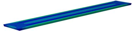
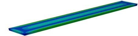
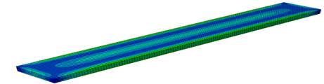
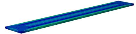
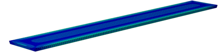
Table 12. Longitudinal stress profile diagram of concrete
|
Materials |
Longitudinal stress profile diagram of concrete |
Indicator |
|
CFRC |
|
|
|
CRC |
|
|
|
MC |
|
|
|
OSWC |
|
|
|
WTSC |
|
In summary, the data analysis clearly demonstrates that differences in Poisson’s ratio—and the associated lateral deformation directly influence the load–displacement behavior and stress distribution across the various concrete schemes. These findings validate the performance benefits of incorporating alternative materials such as CFRC, which offers enhanced ductility and improved load transfer characteristics under compressive loading.
3.2 Reaction Forces along different directions analysis
In general, even with various strain differences appearing among the schemes, the distribution maintains uniformity indicates a relatively robust structural design. These findings serve as a basis for further examinations and work on optimizing structures for more stability and reliability, and through such refinements, to lower risks from strain accumulation or deformation in localized spots.
Reaction forces in different directions contribute to observing how nodes respond dynamically across the analysis. The forces RF1, RF2, and RF3 respectively represent the force components on nodes in the X, Y, and Z axes. The sizes of RF1, RF2, and RF3 numerically indicate the nodes’ resistances to external forces across different paths. Simply, reaction forces (RF) are the "push-back" forces generated by support that prevent the structure from moving. RF1 is the reaction force along the X direction, RF2 is the reaction force along the Y-direction, and RF3 is the reaction force along the Z-direction.
Among the three reaction force components (RF1, RF2, RF3), only RF2—corresponding to the loading direction—provides physically meaningful values. RF1 and RF3 exhibit extremely small magnitudes (on the order of 10⁻¹³–10⁻¹⁴), indicating numerical artifacts rather than structural response, and are therefore excluded from further analysis.
In Table 13, CFRC shows a slower growth in reaction force on the Y-axis, attributed to the high compression strength in the concrete slab, eventually leading to a steady level. CRC shows the high strength in concrete compression along the Y-axis causes the reaction force to go up progressively and then reach a stable state. This happens is the concrete slab, with its strong compressive capacity, makes the Y-axis reaction force gradually rise until it evens out. The principles described in MC and WTSC are consistent with those observed in the previously discussed cases, demonstrating comparable load-displacement characteristics. Initially, the system exhibits stability, which is subsequently influenced by structural imperfections and variations in the applied loading conditions.
Table 13. The reaction forces of five materials (RF2)
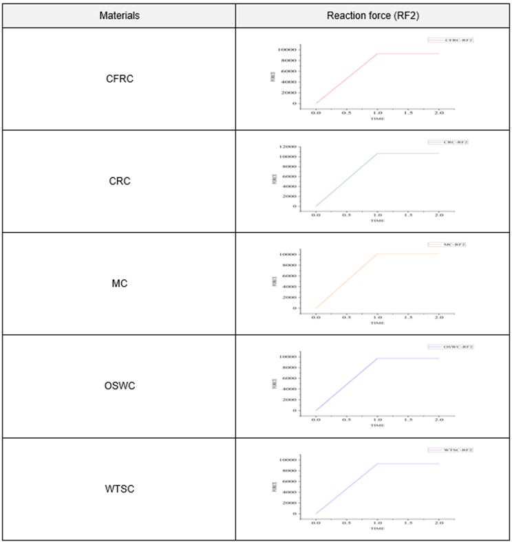
3.3 Comparison of Six Types of Reaction Forces (RF2)
The constrained reaction force in the Y-direction, imposed through boundary conditions at the nodes, is used to verify whether the support responses satisfy the loading requirements. As shown in Figure 9, CRC exhibits the highest support reaction force, reaching 10,677 N. This suggests a high localized stiffness, likely due to the rubber particles enhancing internal compactness and mechanical resistance. FRC shows the lowest reaction force (9,089 N), which may reflect its ability to distribute stress uniformly and minimize performance fluctuations, thereby ensuring reliable performance under varying conditions. The constrained reaction forces for WTSC, CFRC, and MC show minimal variation. Further analysis of Figure 9 confirms that, in the Y-direction, FRC contributes less to the structural load resistance, while CRC demonstrates a significantly higher stiffness demand.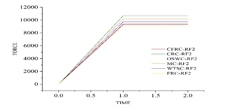
Fig. 9. Reaction force comparison (RF2)
The reaction force behavior of CFRC, CRC, MC, OSWC, and WTSC was modeled using second-degree polynomial equations, which better capture the non-linear response observed during loading. These polynomial expressions provide a more accurate representation of how the materials behave under increasing loads, particularly beyond the elastic region. The equations are as follows:
| \[{y_{CFRC}}_=-0.436x2\ +\ 135.14x\ -\ 695.83\] | (17) |
| \[{y_{CRC}}_=-0.4956x2\ +\ 153.59x\ -\ 790.85 \] | (18) |
| \[{y_{MC}}_=-0.471x2\ +\ 145.98x\ -\ 751.65 \] | (19) |
| \[{y_{OSWC}}_=-0.4514x2\ +\ 139.89x\ -\ 720.29\] | (20) |
| \[{y_{WTSC}}_=\ -0.4317x2\ +\ 133.8x\ -\ 688.94 \] | (21) |
| \[{R_{CRC}^2}^=0.9873 \] | (22) |
| \[{R_{MC}^2}^=0.9873\] | (23) |
| \[{R_{OSWC}^2}^=0.9873\] | (24) |
| \[{R_{WTSC}^2}^=0.9873\] | (25) |
In these equations, x represents displacement (in mm), and y represents the reaction force (in kN). The negative quadratic coefficients indicate a concave-down curve, which is typical in materials that exhibit peak load followed by softening, possibly due to cracking or material degradation. CRC demonstrates the highest peak stiffness and reaction force, as indicated by its larger linear and quadratic coefficients. WTSC, on the other hand, has the lowest values, suggesting reduced load-bearing capacity and stiffness.
All models show strong correlation with the experimental data, as reflected by their high coefficients of determination (R2=0.9873, Equations 22–25). This consistency across all concrete types reinforces the reliability of the polynomial fit in capturing the materials' actual load-deformation behaviours.
3.4 Flexural Tensile strength
Flexural tensile strength, also called the modulus of rupture, is a key parameter that indicates when tensile cracking begins under bending—it typically measures 10–20% of compressive strength and is crucial for evaluating concrete’s serviceability in bending scenarios, such as slabs and pavements. As shown in Table 14, the measured average 28-day flexural tensile strengths for the waste-modified mixes are:
Table 14. Average 28-day flexural tensile strengths for the waste-modified mixes
|
Material |
Waste materials content (%) |
Bending strength (N/mm² = MPa) |
|
CFRC |
2.5 |
3.72 |
|
CFRC |
3.0 |
3.83 |
|
CFRC |
3.5 |
3.65 |
|
CRC |
2.5 |
4.00 |
|
CRC |
3.0 |
4.55 |
|
CRC |
3.5 |
4.41 |
|
MC |
2.5 |
3.54 |
|
MC |
3.0 |
3.63 |
|
MC |
3.5 |
3.60 |
|
OSWC |
2.5 |
3.2 |
|
OSWC |
3.0 |
3.16 |
|
OSWC |
3.5 |
3.08 |
|
WTSC |
2.5 |
3.525 |
|
WTSC |
3.0 |
4.585 |
|
WTSC |
3.5 |
3.317 |
CFRC demonstrated peak flexural strength at 3.0% fiber content (approximately 3.85 MPa), representing a marginal enhancement over plain concrete (3.7 MPa). This indicates that coconut fibers effectively delay crack initiation while improving flexural capacity and ultimate strength. CRC achieved significantly higher flexural strength (4.55 MPa at 3.0% rubber content), substantially outperforming conventional concrete formulations. MC maintained flexural strength within the 3.54-3.63 MPa range, comparable to conventional concrete performance, this suggesting mining waste replacement does not detrimentally affect flexural properties. OSWC exhibited lower flexural capacity (3.08-3.20 MPa) among the tested composites. Conversely, WTSC demonstrated superior performance with 4.585 MPa strength at 3.0% sludge incorporation, exceeding conventional concrete benchmarks.
The ranking of bending performance among the waste modified concrete mixes is as follows:
WTSC > CRC > CFRC > MC ≈ OSWC. WTSC exhibits superior flexural performance, surpassing conventional concrete in ultimate strength and ductility. CFRC shows moderate improvement through a crack bridging mechanism, enhancing toughness with minimal strength gain. MC and OSWC both maintain flexural properties comparable to the control mix. CRC sacrifices a degree of ultimate strength but achieves significant ductility gains, offsetting its strength loss. Notably, WTSC achieves the highest flexural tensile strength, while CRC and CFRC offer enhanced toughness; MC and OSWC retain acceptable bending capacity.
3.5 Recommendations
Future research should focus on enhancing the understanding of key aspects, such as the long-term durability and performance of modified concrete materials under diverse environmental conditions. This includes comprehensive studies on material fatigue and the distribution of concentrated stress to evaluate the risk of structural degradation over time. Moreover, developing innovative reinforcement techniques for high-stress areas—particularly at bending sections and junctions where vertical ribs connect to panels—is crucial. Utilizing advanced modeling tools like ABAQUS can facilitate the simulation of real concrete samples, validate experimental findings, and refine material compositions for improved structural performance. The discrepancies between experimental results and finite element model predictions ranged from 5% to 11%. Addressing these challenges will contribute to optimized structural designs, enhanced material efficiency, and further advancements in sustainable construction practices.
4 Conclusions
This study used Abaqus FEA to simulate the axial compression of concrete slabs made with various waste materials (coconut fiber, crumb rubber, mining aggregate, oyster shell, and water treatment sludge). All slabs were modeled as plain concrete to isolate the effect of the additives. The simulations applied a fixed base and increasing axial load, capturing load–displacement behavior, reaction forces, and flexural strength.
Load–displacement behavior: Among the mixes, WTSC showed the stiffest response and highest load capacity, reaching the largest peak stress (≈0.1016 MPa) suggesting it may best sustain heavy loads. CFRC started with slightly lower stiffness than plain C35 concrete but maintained more load after peak (fiber bridging delayed failure), implying improved ductility. CRC was notably soft initially (due to rubber inclusions) and deformed the most before failure; it produced the lowest peak stress (≈0.0604 MPa), indicating high toughness at the expense of strength. MC had a curve almost identical to the plain concrete, suggesting its strength and stiffness were largely unaffected by the waste aggregate. OSWC began below the control in stiffness and strength, showing only moderate ductility as shell particles acted as fillers; its performance same to the common concrete.
Reaction forces: Only RF2 was significant. CRC generated the highest support reaction (≈10.7 kN) and CFRC the lowest (≈9.1 kN), aligning with their relative stiffnesses. This implies the rubber-containing mix requires more force to resist deformation (higher localized stiffness), whereas the fiber mix spreads stress more evenly (lower concentrated reaction). The other mixes (WTSC, MC, OSWC) produced reaction forces between these extremes. From stress and strain distribution analysis, designs that exhibited uniform stress and strain patterns, such as those shown in Fig. 13 and Fig. 16, are likely to be more stable and reliable. These insights can inform the optimization of concrete structural design by reinforcing weak zones and choosing the right mix depending on load-bearing requirements.
Flexural strength: WTSC achieved the highest bending strength (≈4.59 MPa at 3.0% sludge), followed closely by CRC (≈4.55 MPa at 3.0% rubber). CFRC peaked at around 3.83 MPa (3.0% fiber), a modest improvement over plain concrete. MC and OSWC remained near 3.6 MPa and 3.1 MPa, respectively (close to control values). In ranking order: WTSC > CRC > CFRC > MC ≈ OSWC in flexural performance. These trends suggest that adding sludge or rubber greatly boosts toughness (and in WTSC’s case strength), fibers give moderate gain, while mining waste or shells have little effect on bending strength.
This study confirms that incorporating waste materials such as coconut fibers, rubber, sludge, and shells not only supports environmental goals like waste reduction and circular economy but also offers viable structural benefits. The combination of lab testing and advanced FEA simulations strengthens confidence in these green concrete types as practical alternatives for sustainable and climate-resilient infrastructure.
4.1 Limitation and improvement
There are obstacles faced, like different results that come up from the kinds and amounts of waste materials put in, and the uncertainties tied to how long-lasting they will prove over time. The need for additional research is present so these questions can be addressed and to discover what mix of these materials might work out best in practice. Another limitation lies in the inherent variability in the composition and quality of waste-derived components, which makes it difficult to obtain consistent material properties for waste-modified concretes such as CFRC, OSWC, and WTSC. This variability can affect the accuracy of input parameters used in numerical simulations, thereby influencing the reliability of comparative analysis. To address this issue, material properties were determined based on the average experimental data from multiple specimens, and standard deviation analysis was conducted to assess variability. Future research may incorporate probabilistic modeling techniques to more accurately capture material heterogeneity and enhance the robustness of the simulations.
Acknowledgements
The authors would like to acknowledge the support of Prince Sultan University (PSU) Riyadh Saudi Arabia for paying the Article Processing Charges (APC) of this publication and thanks to Prince Sultan University for their support. Also, Centre of Excellence for Research, Value, Innovation and Entrepreneurship (CERVIE) UCSI University, Malaysia for providing the facilities of the research (REIG-FETBE-2022/052).
References
- Balasubramanian M. Composite materials and processing[M]. CRC press, 2013.
- Thomas B S, Yang J, Bahurudeen A, et al. Geopolymer concrete incorporating recycled aggregates: A comprehensive review[J]. Cleaner Materials. https://doi.org/10.1016/j.clema.2022.100056.
- Mikhaylov A, Moiseev N, Aleshin K, et al. Global climate change and greenhouse effect[J]. Entrepreneurship and Sustainability Issues. https://doi.org/10.9770/jesi.2020.7.4(21).
- Golewski G L. Green concrete based on quaternary binders with significant reduced of CO2 emissions[J]. Energies. https://doi.org/10.3390/en14154558.
- Nunes L A, Silva M L S, Gerber J Z, et al. Waste green coconut shells: Diagnosis of the disposal and applications for use in other products[J]. Journal of Cleaner Production, 2020, 255: 120169. https://doi.org/10.1016/j.jclepro.2020.120169.
- Potluri Anudeep, M. Achyutha Kumar Reddy, Veerendrakumar C. Khed, Musa Adamu, Mada Varalakshmi , Yasser E. Ibrahim and Omar Shabbir Ahmed. 2024. “Effect of superplasticizer in geopolymer and alkali-activated cement mortar/concrete: A review,” J. Reviews On Advanced Materials Science., vol.63 (1), p. 1-19, doi: 10.1515/rams-2023-0173.
- Musa Adamu a, Yasser E. Ibrahim a, Hani Alanazi, 2024. “Optimization of sustainable concrete properties modified with blends of date palm ash and eggshell powder using response surface methodology,” J. Developments in the Built Environment., vol. 17, p. 1-19. doi: 10.1016/j.dibe.2024.100359.
- Musa Adamu * , Yasser E. Ibrahim, 2024. “Environmental sustainability and cost-benefit analysis of concrete containing date palm ash and eggshell powder: A response surface methodology approach,” J. Case Studies in Chemical and Environmental Engineering., vol. 19, p. 1-11, doi: 10.1016/j.cscee.2024.100636
- Qaidi S M A, Dinkha Y Z, Haido J H, et al. Engineering properties of sustainable green concrete incorporating eco-friendly aggregate of crumb rubber: A review[J]. Journal of Cleaner Production. https://doi.org/10.1016/j.jclepro.2021.129251.
- Ahmad J, Zhou Z, Majdi A, et al. Overview of Concrete Performance Made with Waste Rubber Tires: A Step toward Sustainable Concrete[J]. Materials, 2022, 15(16): 5518. https://doi.org/10.3390/ma15165518.
- Habert G, Miller S A, John V M, et al. Environmental impacts and decarbonization strategies in the cement and concrete industries[J]. Nature Reviews Earth & Environment. https://doi.org/10.1038/s43017-020-0093-3.
- Dadkhah M, Tulliani J M. Damage management of concrete structures with engineered cementitious materials and natural fibers: a review of potential uses[J]. Sustainability, 2022, 14(7): 3917. https://doi.org/10.3390/su14073917.
- Shcherban’ E M, Stel’makh S A, Beskopylny A N, et al. Normal-weight concrete with improved stress–strain characteristics reinforced with dispersed coconut fibers[J]. Applied Sciences. https://doi.org/10.3390/app122211734.
- Alomayri T, Ali B. Effect of plant fiber type and content on the strength and durability performance of high-strength concrete[J]. Construction and Building Materials. https://doi.org/10.1016/j.conbuildmat.2023.132166.
- Nunez I, Marani A, Flah M, et al. Estimating compressive strength of modern concrete mixtures using computational intelli gence: A systematic review[J]. Construction and Building Materials, 2021, 310:125279. https://doi.org/10.1016/j.conbuildmat.2021.125279
- Seminara P, Vand B, Sajjadian S M, et al. Assessing and monitoring of building performance by diverse methods[J]. Sustainability, 2022, 14(3): 1242. https://doi.org/10.3390/su14031242.
- Kashyap, S., Datta, D., 2017. Reusing industrial lime sludge waste as a filler in polymeric composites. Materials Today Proceed. https://doi.org/10.1016/j.matpr.2017.02.176
- Oderji S Y, Chen B, Shakya C, et al. Influence of superplasticizers and retarders on the workability and strength of one-part alkali-activated fly ash/slag binders cured at room temperature[J]. Construction and Building Materials. https://doi.org/10.1016/j.conbuildmat.2019.116891 .
- Amran M, Debbarma S, Ozbakkaloglu T. Fly ash-based eco-friendly geopolymer concrete: A critical review of the long-term durability properties[J]. Construction and Building Materials. https://doi.org/10.1016/j.conbuildmat.2020.121857.
- Wang T, Xiao F, Zhu X, et al. Energy consumption and environmental impact of rubberized asphalt pavement[J]. Journal of Cleaner Production, 2018, 180: 139-158. https://doi.org/10.1016/j.jclepro.2018.01.086.
- Ting L, Qiang W, Shiyu Z. Effects of ultra-fine ground granulated blast-furnace slag on initial setting time, fluidity and rheological properties of cement pastes[J]. Powder Technology. https://doi.org/10.1016/j.powtec.2018.12.094.
- Dobiszewska M, Bagcal O, Beycioğlu A, et al. Utilization of rock dust as cement replacement in cement composites: An alternative approach to sustainable mortar and concrete productions[J]. Journal of Building Engineering. https://doi.org/10.1016/j.jobe.2023.106180.
- Tushar Q, Santos J, Zhang G, et al. Recycling waste vehicle tyres into crumb rubber and the transition to renewable energy sources: A comprehensive life cycle assessment[J]. Journal of environmental management, 2022, 323: 116289. https://doi.org/10.1016/j.jenvman.2022.116289.
- Gomes S D C, Zhou J L, Li W, et al. Progress in manufacture and properties of construction materials incorporating water treatment sludge: A review[J]. Resources, conservation and recycling, 2019, 145: 148-159. https://doi.org/10.1016/j.resconrec.2019.02.032
- Marchiori L, Albuquerque A, Cavaleiro V. Water Treatment Sludge as Geotechnical Liner Material: State-of-Art[C]//International Conference on Environmental Geotechnology, Recycled Waste Materials and Sustainable Engineering. Springer, Singapore, 2023: 529-547. https://doi.org/10.1007/978-981-99-4041-7_47.
- Wang J, Xu H, Xu D, et al. Accelerated carbonation of hardened cement pastes: Influence of porosity[J]. Construction and Building Materials. https://doi.org/10.1016/j.conbuildmat.2019.07.088.
- Golewski G L. The phenomenon of cracking in cement concretes and reinforced concrete structures: the mechanism of cracks formation, causes of their initiation, types and places of occurrence, and methods of detection—a review[J]. Buildings. https://doi.org/10.3390/buildings13030765.
- Rezende M A M, Gromboni P P, Corradini P G, et al. Evaluation of Reinforcement Corrosion in Cementitious Composites Modified with Water Treatment Sludge[J]. Journal of the BrazilianChemicalSociety.2023.https://doi.org/10.3390/buildings13030765.
- Almeida J, Ribeiro A B, Silva A S, et al. Overview of mining residues incorporation in construction materials and barriers for full-scale application[J]. Journal of Building Engineering, 2020, 29: 101215. https://doi.org/10.1016/j.jobe.2020.101215.
- Wang X, Fan F, Lai J, et al. Steel fiber reinforced concrete: A review of its material properties and usage in tunnel lining[C]//Structures. Elsevier, 2021, 34: 1080-1098. https://doi.org/10.1016/j.istruc.2021.07.086.
- Bayraktar O Y, Eshtewı S S T, Benli A, et al. The impact of RCA and fly ash on the mechanical and durability properties of polypropylene fibre-reinforced concrete exposed to freeze-thaw cycles and MgSO4 with ANN modeling[J]. Construction and Building Materials, 2021, 313: 125508. https://doi.org/10.1016/j.conbuildmat.2021.125508
- Varhen C, Carrillo S, Ruiz G. Experimental investigation of Peruvian scallop used as fine aggregate in concrete[J]. Construction and Building Materials, 2017, 136: 533-540. https://doi.org/10.1016/j.conbuildmat.2017.01.067.
- Akhtar M E, Elavenil S. EXPERIMENTAL STUDY ON COIR BLENDED CONCRETE STRENGTHENED WITH FLY-ASH AND GRANITE POWDER[J]. 2006.
- Monita, Olivia., Annisa, Arifandita, Mifshella., Lita, Darmayanti. (2015). Mechanical Properties of Seashell Concrete. Procedia Engineering, https://doi.org/10.1016/j.proeng.2015.11.127.
- Bamigboye G O, Okara O, Bassey D E, et al. The use of Senilia senilis seashells as a substitute for coarse aggregate in eco-friendly concrete[J]. Journal of Building Engineering, 2020, 32: 101811. https://doi.org/10.1016/j.jobe.2020.101811.
- Shu H, Zhang P, Chang C C, et al. Agricultural waste[J]. Water Environment Research, 2015, 87(10): 1256-1285. https://doi.org/10.2175/106143015X14338845155660.
- Chen H, Li D, Ma X, et al. Mesoscale analysis of rubber particle effect on young’s modulus and creep behavior of crumb rubber concrete[J]. International Journal of Mechanics and Materials in Design, 2021, 17(3): 659-678. https://doi.org/10.1007/s10999-021-09552-y
- Oderinde P A. Digital Spiritualities: Social Media and Nigerian Pentecostal Churches in Switzerland[J]. 2022.
- Adeniyi A G, Onifade D V, Ighalo J O, et al. A review of coir fiber reinforced polymer composites[J]. Composites Part B: Engineering, 2019, 176: 107305. https://doi.org/10.1016/j.compositesb.2019.107305.
- Mo K H, Alengaram U J, Jumaat M Z, et al. Recycling of seashell waste in concrete: A review[J]. Construction and Building Materials, 2018, 162: 751-764. https://doi.org/10.1016/j.conbuildmat.2017.12.009
- Luo K, Zhang M, Jiang Q, et al. Evaluation of using oyster shell as a complete replacement for aggregate to make eco-friendly concrete[J]. Journal of Building Engineering, 2024, 84: 108587. https://doi.org/10.1016/j.jobe.2024.108587.
- Feng W, Liu F, Yang F, et al. Experimental study on dynamic split tensile properties of rubber concrete[J]. Construction and Building Materials, 2018, 165: 675-687. https://doi.org/10.1016/j.conbuildmat.2018.01.073.
- Wang W, Chouw N. Experimental and theoretical studies of flax FRP strengthened coconut fibre reinforced concrete slabs under impact loadings[J]. Construction and Building Materials, 2018, 171: 546-557. https://doi.org/10.1016/j.conbuildmat.2018.03.149.
- de Araujo Thomaz W, Miyaji D Y, Possan E. Comparative study of dynamic and static Young's modulus of concrete containing basaltic aggregates[J]. Case Studies in Construction Materials, 2021, 15: e00645. https://doi.org/10.1016/j.cscm.2021.e00645.
- Małek M, Jackowski M, Łasica W, et al. An experimental study of possible post-war ferronickel slag waste disposal in szklary (Lower silesian, poland) as partial aggregate substitute in concrete: Characterization of physical, mechanical, and thermal properties[J]. Materials, 2021, 14(10): 2552. https://doi.org/10.3390/ma14102552.
- Rachmawati S H, Hossain Z, Shiau J. Shear strength of soil by using clam shell waste as recycle aggregate[J]. Journal of Agricultural Engineering, 2020, 51(3): 155-160. https://doi.org/10.4081/jae.2020.1043
- Ray S, Mishra A K, Kalamdhad A S. Hydraulic performance, consolidation characteristics and shear strength analysis of bentonites in the presence of fly-ash, sewage sludge and paper-mill leachates for landfill application[J]. Journal of Environmental Management, 2022, 302: 113977. https://doi.org/10.1016/j.jenvman.2021.113977
Conflict of Interest Statement
There are no conflicts affecting the research.
Author Contributions
Data Availability Statement
There is no dataset associated with the study or data is not shared.
Supplementary Materials
There are no supplementary materials to include.