Original Scientific Paper, Volume 23, Number 2, Year 2025, No 1264, pp 191-197
Received: Mar 19, 2023 Accepted: Feb 10, 2025 Published: Jun 15, 2025
DOI: 10.5937/jaes0-46616
SIMPLIFYING SHIP STRUCTURAL OPTIMIZATION THROUGH STRESS-BASED MATERIAL SELECTION
Abstract
The structural integrity of a ship emerges as a crucial factor that significantly impacts the overall weight of the ship's construction. When evaluating ships with identical shapes, a strategically refined structural design can greatly amplify the ship's load-bearing capacity. This optimization, in turn, wields a profound influence over the ship's operational efficiency and its broader environmental impact. A highly successful strategy for achieving structural optimization revolves around the meticulous selection of materials that align with permissible stress thresholds mandated by regulations. This selection process is guided by thorough finite element analysis. Within this study, the pursuit of optimization unfolded through an examination of material variations. The initial phase involves the application of diverse material options for each design iteration while adhering to the minimum thickness stipulated by the classification society's regulations. This iterative process persists until the thickness aligns with the structural requirements necessary to uphold load-bearing resilience. The outcomes of this initial step subsequently provide insights into the possibility of substituting materials with higher-ranked alternatives. The material ranking is established by comparing their yield strengths. The materials investigated in this research encompass Mild Steel, AH32, and AH36. The findings of this study underscore the capacity of thickness optimization to significantly reduce the weight of a ship's construction.
Highlights
- Introduced a two-step optimization combining material selection and thickness adjustment to reduce ship structural weight.
- Demonstrated effectiveness of high-yield materials (AH32, AH36) in minimizing plate thickness while meeting stress constraints.
- Proposed a simplified material upgrade strategy with clustering to enhance applicability in shipbuilding.
Keywords
Content
1 Introduction
While being an exceptionally efficient means of transporting goods in terms of emissions generated per kilometer traveled [1], the shipping industry still contributes approximately 2.9% of the total carbon dioxide emissions (CO2), 11% of sulfur oxide (SOx), and 15% of nitrogen oxide (NOx) emissions as of 2018 [2]. To address this, the International Maritime Organization (IMO) has enacted a comprehensive strategy aimed at curbing greenhouse gas (GHG) emissions. The IMO's goal is to achieve a minimum 50% reduction in emissions by 2050 compared to 2008 levels, with further aspirations to attain complete emissions neutrality by 2100 [3]. Presently, the energy efficiency benchmark employed is the Energy Efficiency Design Index (EEDI). This index factors in CO2 emissions, deadweight tonnage (DWT), and distance covered. One approach to fulfilling stringent EEDI criteria, particularly in 2020, involves minimizing the lightweight tonnage (LWT) to facilitate the design of streamlined ships. The integration of this sleek ship design with traditional engines presents itself as a highly competitive solution. Furthermore, the combination of this streamlined shape with a hybrid propulsion system holds the potential to meet the EEDI standards set for 2025 [4]. Nonetheless, in a study by Pruyn J.F.J (2020), it is recommended that careful consideration is given not only to the ship's weight but also to factors like speed and power to enhance overall efficiency [5]. When ships share the same block coefficient and dimensions, the reduction in empty ship weight corresponds to an increase in cargo-carrying capacity. This alignment provides a motivating incentive to diminish emissions from a comprehensive lifecycle perspective [6].
When examining the life cycle dimensions of a ship's hull, the focus naturally centers on three distinct stages: shipbuilding, maintenance, and recycling. Within these phases, efforts can be concentrated on minimizing emissions stemming from the hull. Achieving this reduction is possible through the strategic optimization of steel raw material consumption, thereby impacting the decrease in lightweight tonnage (LWT) and consequently leading to an overall reduction in ship emissions [7]. Notably, a reduction of LWT by 11% yields a notable decrease in the proportion of CO2 emissions, ranging from around 2% to 5% [8]. Steel is chosen as a hull material, ship structure, outfitting, and others. As a result, the emissions produced by steel become large. Steel stands as the primary material of choice for various hull-related aspects including ship structure, outfitting, and more. However, this preference for steel significantly contributes to emissions. In fact, steel production alone accounts for a staggering 90% of the total CO2 emissions generated during the ship construction and maintenance processes. Given this reality, a concerted effort is essential to create optimal designs that capitalize on the potential for cost and energy savings throughout the entirety of the ship's developmental and operational phases [9].
Numerous studies have delved into material selection, all with the common objective of minimizing production costs; these studies, however, employ diverse methodologies. For instance, Yang et al. (2017) [10] harnessed Fuzzy Technique in creating a material selection process. On a similar note, Mehmood, Haneef, and Udrea (2018) [11] adopted Ashby’s approach to material selection for MEMS. In an alternative approach, Putra and Kitamura (2021) introduced a genetic algorithm to drive the material selection process. Nevertheless, this study takes a different approach by leveraging Finite Element Analysis (FEA) to streamline the optimization process without significantly increasing computational time. The research aims to reduce ship weight by integrating material selection and plate thickness optimization. FEA serves as the primary optimization tool, beginning with the downgrading of all plate materials to the lowest grade. This initial downgrading step facilitates material selection, simplifying the optimization process. Subsequently, size optimization is conducted to ensure that maximum stress remains within allowable limits. The final phase involves identifying plates that require reinforcement, determined based on factors such as thickness and surface area.
2 Materials and methods
2.1 Material selection
Material selection encompasses a multitude of factors, including mechanical properties, cost, availability, and environmental impact [12]. Making an erroneous choice in material can result in failure, entailing not only significant costs but potentially catastrophic consequences. The process of establishing material ranking is notably uncomplicated, primarily hinging on the highest yield stress value, as illustrated in Figure 1. Similarly, the notion of material upgrading adheres to a straightforward principle: when the thickness of the existing material surpasses the designated minimum thickness, the upgrading protocol is initiated. Given that the overarching optimization objective is the reduction of structural weight, the transition to a material with a higher yield strength is expected to correspondingly lead to a reduction in thickness.

Fig. 1. Upgrading material strategy
Material selection is based on the number of clusters, where each cluster contains the same type of material. In practice, having too many material types can complicate the material procurement and fabrication processes. Therefore, there is a need for streamlining the process in the hopes of facilitating easy application within the shipbuilding industry. Utilized in this study is the design of an 85,000 LTDW Oil Tanker with midship construction, depicted in Figure 2. The structural components are methodically categorized into three distinct clusters. Specifically, cluster 1 encompasses members situated within the double bottom area, cluster 2 pertains to the members in the cargo oil tank region, and finally, cluster 3 encompasses the structural elements within the deck area. This organized division of structural members into clusters facilitates a systematic analysis and optimization process, catering to the specific requirements and functions of each designated area.
![]()
Fig. 2. Oil tanker midship construction
2.2 Thickness updating
The proposed approach involves a dual process: one focuses on selecting the appropriate material type for the plate, and the other on determining the optimal plate thickness through a dedicated optimization method. Commencing with an initial selection of material, encompassing MS, AH32, and AH36, the algorithm moves forward. The ensuing phase involves identifying plates warranting enhancement and subsequently replacing them with more suitable material types. This iterative process advances until the final stage, where the goal is to minimize the objective function f, signifying the construction weight. The optimization algorithm, meticulously outlined in Figure 3, offers a comprehensive depiction of the step-by-step execution of the proposed methodology. By amalgamating Finite Element Analysis (FEM) with optimization algorithms, a potent avenue emerges for streamlining the material selection process and optimizing plate structure dimensions. This synergy effectively enhances both material selection and structural optimization, underscoring a sophisticated approach to shipbuilding enhancement.
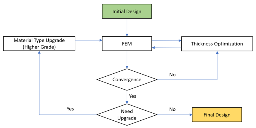
Fig. 3. Oil tanker midship construction
The process of thickness optimization aims to acquire the optimal plate thickness while adhering to stress constraints. The stress constraints employed in this context are linked to the maximum stress experienced by the plate. Equation 1 establishes the correlation between bending moment, axial force, plate thickness, and stresses [13]. The equation below demonstrates the estimation of thickness for the maximum stress condition, wherein signifies the updated thickness, represents the initial thickness, signifies the initial plate maximum stress, and σ_c represents the stress constraint.
 |
(1) |
2.3 Optimization model
2.3.1 Finite element model
The objective of this study is to optimize the weight of the model by selecting the appropriate plate material type and reducing the plate thickness, all while ensuring compliance with class regulations based on stress constraints. The provided design from the shipyard company serves as the model's dimensions and load. Four distinct material combinations were considered for determining the suitable material type. The optimization process commences with an analysis of the model using the minimum thickness scantling through Finite Element Analysis (FEA). This scantling adheres to the guidelines set forth by DNV GL - Rules for Classification and Construction [14]. The net scantling thickness is employed for strength calculations conducted via FEA [15].
Table 1. Initial data
|
Item |
Unit |
1st model |
2nd model |
3rd model |
4th model |
|
L (length) |
mm |
28,700 |
28,700 |
28,700 |
28,700 |
|
B (breadth) |
mm |
44,000 |
44,000 |
44,000 |
44,000 |
|
H (height) |
mm |
21,500 |
21,500 |
21,500 |
21,500 |
|
Load (moment) |
kN.m |
4,100,000 |
4,100,000 |
4,100,000 |
4,100,000 |
|
Initial material type |
- |
All Mild Steel |
All AH32 |
All AH36 |
As-built (AH32-MS-AH32) |
2.3.2 Design variables
Within this study, the selected design variables encompassed the plate material type and the plate thickness. The exploration of material combinations hinged on three distinct material types, as detailed in Table 2. This deliberate selection of design variables and material types serves as the foundation for the subsequent comprehensive analysis and optimization endeavors.
Table 2. Material properties
|
Material Type |
Young Modulus (MPa) |
Density (kg/m3) |
Poisson Ratio |
Yield Strength (MPa) |
|
Mild Steel |
200,000 |
7850 |
0.3 |
235 |
|
AH32 |
200,000 |
7850 |
0.3 |
315 |
|
AH36 |
200,000 |
7850 |
0.3 |
355 |
2.3.3 Design constraints
In this study, the focus is on a specific limit for how much stress the material can handle. To ensure it stays within this limit, we use the recommendations given by IACS rules, particularly those concerning the use of high-tensile steel as shown in Table 3. These rules play a crucial role in maintaining the safety and reliability of our approach, and we'll explore them further in the upcoming sections.
Table 3. Material allowable stress
|
Material Type |
Yield Strength (MPa) |
Allowable Stress (MPa) |
Allowable / Yield Factor |
|
Mild Steel |
235 |
190 |
0.81 |
|
AH32 |
315 |
244 |
0.77 |
|
AH36 |
355 |
264 |
0.74 |
2.3.4 Objective function
The primary aim of this study revolves around making the midship section of the structure lighter by utilizing thinner plates. This goal is measured using a specific equation known as Equation 2. By comprehending this objective and the equation's role, a clearer understanding of the research's focus and approach is gained.
 |
(2) |
where:
M = total mass
N = total plate number
$\rho $ = material density
$A_i$= plate surface area
$t_i$ = plate thickness
3 Results and discussion
To assess the effectiveness of the proposed method, the optimization process is conducted across four distinct models, each featuring different material types. This method involves the replacement of materials through upgrades, coupled with the optimization of plate thickness. Through this systematic testing on varied models, we gain valuable insights into the method's capabilities and its potential for enhancing the overall efficiency of the shipbuilding process.
The initial optimization is performed on models employing mild steel as the chosen material type. In Figure 4a, the additional thickness of several structure components is displayed. These components encompass items numbered 5 & 6, specifically the bilge plate for the bottom area, as well as numbers 47, 48, and 49 associated with the deck area. Notably, the deck area encounters a notable increase in thickness, approaching the as-built maximum limit of 20.5 mm. However, when the material upgrade process is implemented, the thickness of the plate experiences a significant reduction, particularly affecting the bilge plate. While the material upgrade process may lead to an increase in the bilge plate's thickness, it still proves advantageous by enabling a reduction in the deck plate's thickness. The deck plate covers an extensive area of 631.75 m2, whereas the bilge plate occupies a smaller space of 101.43 m2. Assuming a steel density of 7850 kg/m3 and both plates being 1 mm thick, the deck plate's weight amounts to 4.96 tons, in contrast to the bilge plate's mere 0.8 tons. Consequently, by decreasing the deck plate's thickness by 6.5 mm and augmenting the bilge plate's thickness by 4 mm, a substantial decrease in the overall material weight is achieved.
In the second optimization phase, the highest stress emerges in the bilge plate starboard, reaching 239.07 MPa with an 11 mm thickness. Conversely, upon upgrading the material for items numbered 47, 48, and 49 (cluster 3) from AH32 to AH36, the center bulkhead 8 encounters a maximum stress of 262.02 MPa, featuring a 14 mm thickness. Remarkably, this upgrade results in an increased thickness for center bulkhead 8, progressing from 11 mm to 14 mm. This adjustment is made possible by decreasing the deck plate's thickness, a strategic choice that optimizes weight distribution given the deck plate's larger surface area. The representation shown in Figure 4b above illustrates the additional thickness incorporated into various structural components, including items numbered 3 & 4 (bottom plate) and 5 & 6 (bilge plate) within cluster 1, along with the components within the deck area. As a result, the deck area experiences a relatively minor increase in thickness when compared to the variations involving All Mild Steel (1st Model).
|
(a) |
(b) |
|
(c) |
(d) |
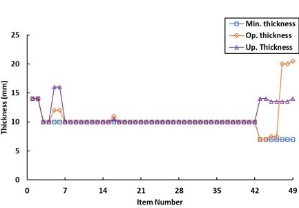
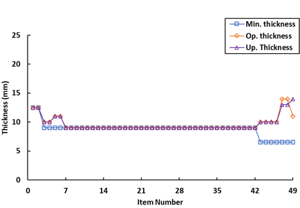
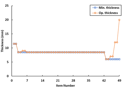

Fig. 4. The optimal plate thickness (a) All Mild Steel (b) All AH32 (c) All AH36 (d) As Built
During the third optimization phase, the center bulkhead 8 encounters a maximum stress value of 262.69 MPa, possessing a thickness of 20 mm. Figure 4c provides a visual representation of the added thickness applied to various structural components. These include items numbered 5 & 6 (bilge plate) within cluster 1, along with select items within the deck area. Remarkably, center bulkhead 8 experiences a notable thickness augmentation of up to 20 mm, compared against the minimum thickness, which signifies an increase of 6 mm.
In the fourth optimization stage, the maximum stress value of the AH32 material is observed in the bilge plate portside, measuring 237.51 MPa with a thickness of 11.5 mm. Simultaneously, the maximum stress value for the Mild Steel material is noted in center bulkhead 1, reaching 189.52 MPa and maintaining a thickness of 11.5 mm. An interesting observation is that the lowest stress concentration occurs within cluster II, which consists of items located near the neutral axis of the model. This characteristic permit cluster II items to possess a thickness that adheres to the specified minimum. On the other hand, cluster I and cluster III items experience the highest stress concentration. Illustrated in Figure 4d is the incremental thickness added to various components, including items numbered 5 & 6 (bilge plate) within cluster 1, number 36 (center bulkhead 1), and components within the deck area. In the as-built combination, no significant increase in thickness is discernible. However, there is a distinctive response compared to other combinations, primarily manifested through the augmentation of center bulkhead 1.
Figure 5 presents a comparative depiction of the stress ratio, illustrating the relationship between the generated stress and the material's yield strength value. The graph clearly highlights a pattern where elevated stress ratios are prevalent in the As Built and Full MS Models, whereas relatively lower ratios are observed in the AH32 and AH36 models. Figure 6a reinforces this analysis by indicating that the highest total stress ratio emerges in the as-built model, while the lowest is evident in the AH36 model. This underscores the fact that the plates resulting from optimization in the MS and As-Built models closely approach the stress constraint limit. In contrast, the AH36 model's ratio is comparatively low, due to the imposition of a minimum thickness constraint that prevents further thinning to attain the stress constraint.
Figure 6b showcases a distinct trend, wherein despite AH36 boasting a lower stress ratio, it yields the lightest weight among the models, closely followed by the AH32 model. This aligns with AH36's material characteristics, characterized by a high yield strength value. Consequently, thinner plates of AH36 can achieve the same stress levels as thicker materials with lower yield strengths.
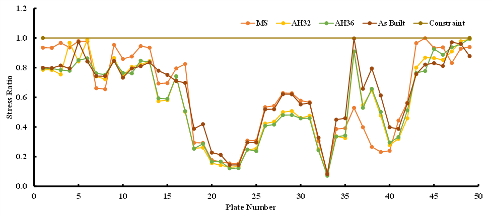
Fig. 5. Stress distribution (a) All Mild Steel (b) All AH32 (c) All AH36 (d) As Built
|
(a) |
(b) |
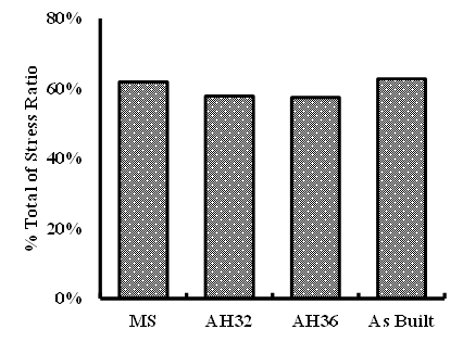
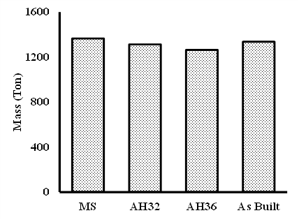
Fig. 6. Comparison of Stress Ratio (a); and Mass (b)
4 Conclusions
The optimization process within this algorithm unfolds in two distinct stages. The first stage involves the implementation of a method designed to select the most suitable plate material type. This strategic choice sets the foundation for the subsequent phase. In the second stage, a thickness optimization method comes into play, with its primary objective centered around determining the optimal plate thickness. This dual-stage approach ensures a comprehensive and nuanced optimization process that addresses both material selection and structural dimensions.
The outcome of these optimization efforts presents a compelling insight. By considering the interplay of material combinations, a tangible reduction in the overall weight of the ship's structure is achieved. This demonstrates the practical significance of the proposed method in enhancing the efficiency and performance of ship design. A notable highlight emerges from the utilization of two distinct material types in the optimization process. This combination proves to be particularly effective in managing structures subjected to relatively high levels of stress. Through this approach, the design successfully strikes a balance between achieving lighter weight and lower plate thickness, ultimately contributing to the overall optimization of the ship's structural integrity.
Acknowledgements
This work was supported by the PUTI Q2 Research Grant 2025, Universitas Indonesia. The authors would like to express their sincere gratitude for the financial support provided, which enabled the successful completion of this research.
References
- Pérez Osses JR, Palma VM, Reusser CA, Contreras J. Emissions assessment of a tanker in a chilean port using bi-directional cold ironing integrated to LNG. Sustainable Energy Technologies and Assessments. 2022 Aug 1;52.
- Comisión Europea Dirección General de Acción por el Clima., CE Delft. STUDY on methods and considerations for the determination of greenhouse gas emission reduction targets for international shipping : Final report Technology Pathways. Publications Office of the European Union; 2019.
- International Maritime Organization (IMO). AMENDMENTS TO THE ANNEX OF THE PROTOCOL OF 1997 TO AMEND THE INTERNATIONAL CONVENTION FOR THE PREVENTION OF POLLUTION FROM SHIPS, 1973, AS MODIFIED BY THE PROTOCOL OF 1978 RELATING THERETO (Inclusion of regulations on energy efficiency for ships in MARPOL Annex VI). 2011.
- Lindstad E, Bø TI. Potential power setups, fuels and hull designs capable of satisfying future EEDI requirements. Transp Res D Transp Environ. 2018 Aug 1;63:276–90.
- Pruyn JFJ. Benchmarking bulkers delivered between 2010 and 2016, identifying the effect of the EEDI introduction. Journal of Shipping and Trade. 2020 Dec;5(1).
- Chatzinikolaou SD, Ventikos NP. Applications of Life Cycle Assessment in Shipping SAFEDOR View project IMO work on FSA View project Stefanos Chatzinikolaou RINA Services [Internet]. 2014. Available from: https://www.researchgate.net/publication/280313533
- Dong DT, Cai W. Life-cycle assessment of ships: The effects of fuel consumption reduction and light displacement tonnage. Proceedings of the Institution of Mechanical Engineers Part M: Journal of Engineering for the Maritime Environment. 2020 Feb 1;234(1):143–53.
- Amer Y, Wang R, Abdullatif LD. Minimizing Ship Weight and an Investigation of Sustainability. 2012;
- Palomba G, Scattareggia Marchese S, Crupi V, Garbatov Y. Cost, Energy Efficiency and Carbon Footprint Analysis of Hybrid Light-Weight Bulk Carrier. J Mar Sci Eng. 2022 Jul 1;10(7).
- Yang SS, Nasr N, Ong SK, Nee AYC. Designing automotive products for remanufacturing from material selection perspective. J Clean Prod. 2017 Jun 1;153:570–9.
- Mehmood Z, Haneef I, Udrea F. Material selection for Micro-Electro-Mechanical-Systems (MEMS) using Ashby’s approach. Mater Des. 2018 Nov 5;157:412–30.
- Emovon I, Oghenenyerovwho OS. Application of MCDM method in material selection for optimal design: A review. Results in Materials. 2020 Sep 1;7.
- Putra GL, Kitamura M. Material Cost Minimization Method of the Ship Structure Considering Material Selection. J Mar Sci Eng. 2023 Mar 1;11(3).
- [Lloyd GS. Rules for Classification and Construction III Naval Ship Technology 1 Surface Ships 1 Hull Structures and Ship Equipment [Internet]. 2012. Available from: www.gl-group.com
- IACS. Requirements concerning strength of ships: Evaluation of Scantlings of Hatch Covers and Hatch Coamings and Closing Arrangements of Cargo Holds of Ships. 2023.
Conflict of Interest Statement
The authors declare that there are no conflicts of interest regarding the publication of this paper.
Author Contributions
Data Availability Statement
No supplementary materials were provided for this study.
Supplementary Materials
There is no dataset associated with the study or data is not shared.