Volume 23 number 3 article 1293 pages 558-574
Received: Apr 21, 2025 Accepted: Aug 13, 2025 Available Online: Aug 27, 2025 Published: Sep 15, 2025
DOI: 10.5937/jaes0-58360
SUSTAINABILITY ANALYSIS OF LIGHTWEIGHT CONCRETE TECHNOLOGIES: OPTIMIZING CLC PANEL THICKNESS FOR STRUCTURAL PERFORMANCE AND ENVIRONMENTAL FOOTPRINT REDUCTION
Abstract
This research examines the optimization of Cellular Lightweight Concrete (CLC) panel thickness to balance structural performance with environmental sustainability for construction on soft, peaty terrain in West Kalimantan, Indonesia. Laboratory testing was conducted on precast CLC slab panels (1,600 mm × 600 mm) with thicknesses varying from 70 mm to 130 mm. The panels were fabricated using a mixture of foam agent, cement, water, and sand, resulting in specimens with an average density of 1,287.26 kg/m³, while achieving a compressive strength of 3.42 MPa. The unidirectional slabs with double M5 (wiremesh) reinforcement were tested after a 28-day curing period. Results showed that thicker panels exhibited superior bending load capacity, with L/240 design flexural capacity ranging from 1.61 kN to 6 kN for thicknesses between 70 mm to 130 mm. Analysis determined that panels exceeding 100 mm thickness successfully sustained the design load of 250 kg (25 kN) minimum load for flexural capacity, making them suitable for 1,600 mm spans. The study establishes a minimuml thickness threshold that balances minimal material usage with adequate structural performance, offering an environmentally responsible building solution that reduces material consumption, transportation energy requirements, and foundation loads for problematic soil regions.
Highlights
- Thicker Cellular Lightweight Concrete (CLC) panels exceeding 100 mm provide adequate support for the necessary design load across 1,600 mm spans, achieving a balance between structural strength and material efficiency.
- Optimizing CLC panel thickness presents a sustainable construction approach by minimizing material consumption, lowering transportation energy requirements, and decreasing foundation loads on soft, peaty soils.
- Laboratory results indicate that an increase in CLC panel thickness markedly enhances flexural capacity, thereby ensuring adequate structural performance.
Keywords
Content
1 Introduction
The construction industry stands at a critical juncture where sustainable building practices have become imperative amidst growing environmental concerns. Cellular Lightweight Concrete (CLC) technology has emerged as a promising alternative to conventional building materials, offering significant potential for reducing the construction sector's ecological footprint while maintaining structural integrity. The optimization of CLC panel thickness represents a crucial area of research that directly impacts both the material's performance capabilities and its environmental sustainability profile. By strategically determining optimal panel dimensions, engineers and architects can maximize strength-to-weight ratios while minimizing resource consumption, thereby addressing the dual challenges of structural reliability and environmental responsibility that contemporary construction faces [1].
The structural performance of CLC panels is intrinsically linked to their dimensional specifications, with thickness being a primary determinant of load-bearing capacity and durability. Research indicates that CLC can achieve compressive strengths of up to 3.417 MPa [2], making it a viable replacement for traditional brick masonry in various applications. However, the relationship between panel thickness and structural integrity is not linear and must be carefully calibrated according to specific construction requirements and seismic considerations [3]. The manufacturing process plays a pivotal role in this optimization, as varying foam content, cement-to-foam ratios, and curing techniques significantly influence the panels' density, strength, and long-term performance characteristics. This necessitates a comprehensive analysis that considers both immediate structural demands and lifecycle performance metrics when determining optimal panel configurations.
The soil conditions in the construction site feature a porous structure and peat land, which have a low bearing capacity and are prone to substantial subsidence when subjected to loads. These soil characteristics pose challenges for construction, often requiring specialized treatment to mitigate the burden on the structure. One approach to address this issue is the use of lightweight concrete precast panels CLC for the building slab. Lightweight concrete represents a significant advancement in sustainable construction technology, offering substantial benefits for structural applications while addressing environmental concerns in the building industry [4]. Lightweight concrete can be classified into three primary categories based on application: structural lightweight concrete (1400-1920 kg/m³ with compressive strength ≥17 MPa), masonry concrete (500-800 kg/m³ with 7-17 MPa strength), and insulating concrete (<800 kg/m³ with 0.7-7 MPa strength) [5]. Compared to traditional concrete, CLC panels have a significantly lower volume weight, typically ranging from 600 to 1,800 kg/m³, whereas standard lightweight concrete has a volume weight of 1,200 to 1,800 kg/m³ [4]. By substituting conventional concrete with CLC panels for the building slab, the overall structural load can be reduced per square meter of the slab area. This load reduction strategy can be particularly beneficial in construction projects on soft soil or peat land, where minimizing the burden on the ground is crucial to ensure the structural integrity and stability of the building [6].
Cellular Lightweight Concrete is a concrete variant notable for its exceptional thermal insulation capabilities and low density. This lightweight material, suitable for construction projects, is produced by blending cement, aggregates, water, and a foaming agent. CLC has been utilized in a wide range of applications beyond acoustic and insulation purposes, including the construction of walls, floors, and roofs [7]. Its energy efficiency and versatility make it a preferred choice for sustainable building practices. CLC is recognized for its superior sound insulation, thermal insulation, and eco-friendly properties, as it exhibits lower density, load, water absorption, and environmental impact compared to traditional concrete alternatives [8]. Cellular Lightweight Concrete has a high degree of adaptability, so it can be easily formed into various shapes and sizes. Because Cellular Lightweight Concrete is a lightweight concrete. This versatility facilitates the creation of innovative and distinctive architectural designs. Furthermore, building owners benefit significantly from CLC lightweight floor panels as the load received will be smaller, which impacts the size of the structure used. This will save on materials and costs. Given its numerous advantages, it is unsurprising that CLC is emerging as a preferred choice for sustainable and eco-friendly building materials within the construction industry [9]. Sand as one of the basic ingredients of CLC masonry concrete brick maker is a grain binder and cement into a solid foam [10].
In addition, CLC is notable for its low drying shrinkage, low porosity, high sound resistance, and high thermal conductivity and low volume weight below 1,000 kg/m3, making it a reliable choice for structures in areas with poor soil structure and earthquake prone. As a result, the lightweight nature of CLC can reduce the overall weight of the building, leading to decreased structural requirements and lower foundation costs. In general, the utilization of CLC in construction not only offers a cost-effective solution for builders who want to build structures in areas with poor soil structure, earthquake prone and environmentally friendly, but also provides a sustainable alternative. These CLC masonry concrete bricks are environmentally friendly [11]. Understanding these long-term behavioral characteristics is essential for developing design guidelines and performance criteria that enable the widespread adoption of sustainable concrete technologies in structural applications while maintaining adequate service life and structural integrity throughout the design period [12].
Examining the impact of CLC panel thickness on flexural strength is crucial for understanding how variations in thickness can influence the overall structural integrity of buildings. By evaluating the performance of CLC panels with different thicknesses under various stress conditions, researchers can determine the optimal thickness to maximize flexural strength while minimizing material usage. This research provides valuable insights for engineers and architects, enabling them to make informed decisions in the design of CLC panel slab-based structures, ensuring the supportability and thickness of the floor slabs used in the design of CLC panel slab-based structures, ensuring the support capacity and thickness of the floor slab used. Ultimately, investigating the influence of CLC panel thickness on flexural strength will drive the ongoing advancement and enhancement of sustainable building practices. In the production of CLC lightweight slab panels, the primary considerations are the thickness and flexibility requirements prescribed by the L/240 In the production of CLC lightweight slab panels, the primary considerations are the thickness and flexibility requirements prescribed by the L/240 [13], a one-way slab is a structural element designed to transmit loads directly to the supporting beams on both parallel sides. This plate has a length-to-width ratio of ≥ 2, so that the bending moment and shear force are dominant along the longer span direction. The maximum allowable deflection of the floor plate [13]. Concrete standard. Panels with greater thickness will be heavier, but the goal is to facilitate installation by workers. The key requirement is that the panels meet the maximum flexibility criteria of L/240. Therefore, the implementation of CLC lightweight precast panels can serve as an effective solution to the construction challenges posed by peatland regions. By employing this technology, infrastructure development can be made more environmentally friendly, sustainable, affordable, lightweight, and efficient.
2 Materials And Methods
2.1 Materials for CLC Slab Panel
Material analysis aims to determine the properties of materials or ingredients that will be used in mixing mortar and lightweight foam slab panel mixture. The results of the material test data will then be used for the calculation of the design of the mortar mixture for the manufacture of test samples. The materials used: PCC cement, fine aggregate, foam agent, Wiremesh M5. The mixture for CLC slab panel concrete is obtained in Table 1 as follows:
Table 1. Job Mix of CLC Panel Precast/m3
|
Material |
Weight (Kg) |
||
|
Cement |
394 |
||
|
Water |
236 |
||
|
Foam Agent |
21 |
||
|
Fine Aggregate |
515 |
||
|
Total |
1,145 |
Complementary to these panel specimens, cylindrical samples with uniform dimensions of 150 mm in diameter and 300 mm in height were prepared using identical mix proportions and curing protocols to facilitate standardized compressive strength assessment in accordance with ASTM C39 testing procedures. All specimens were produced using the predetermined CLC formulation with consistent foam content percentage and cement-to-aggregate ratios to minimize compositional variables that might influence mechanical performance outcomes.
And wiremesh used in research is obtained in Fig. 1 and Table 2 as follows:
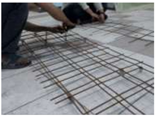
Fig. 1. Wiremesh M5
Table 2. Technical Specifications of Wiremesh M5
|
Specification |
Description |
|
Diameter |
5 mm |
|
Sheet Size |
2.1m x 5.4 m |
|
Load per Sheet |
±24.14 kg |
|
Spacing (Distance between wires) |
150 mm x 150 mm |
|
Tensile Strength |
490 MPa |
|
Bending Strength |
400 MPa |
|
Elongation |
Min. 8% (for SNI standard) |
2.2 Testing Procedures for Determining Optimal Thickness
2.2.1 CLC Lightweight Slabs Model
The following is the modeling of the application of CLC lightweight precast Slab panels in Fig. 2 and Tag. 3 as follows:

Fig. 2. Front View of CLC Precast Slab Panel

Fig. 3. Side View of Precast CLC Slab Panel
Following casting, specimens underwent a standardized 28-day curing regimen in a temperature-controlled environment (23±2°C) at relative humidity exceeding 95%, ensuring uniform hydration conditions prior to experimental testing. This methodical approach to specimen preparation established the fundamental control parameters necessary for subsequent comparative analysis of thickness-dependent flexural performance characteristics.
2.3 Data Analysis Methods
This comprehensive documentation of the manufacturing process provides readers with a thorough understanding of the potential impact these variables may have on the flexural strength of the final product. By delineating the precise procedures involved, the study enables readers to replicate the research and potentially build upon the findings in their own investigations. Furthermore, any deviations or variations from conventional CLC panel production methods are meticulously documented and explained within this section. The study adopted an experimental approach, involving the fabrication and assessment of multiple test specimens, in accordance with the standardized testing protocols established by the American Society for Testing and Materials and the Indonesian National Standard, to obtain the necessary data. Furthermore, the statistical treatment of experimental data through multivariate analysis techniques allows for robust identification of critical threshold values and optimal processing windows, transforming qualitative production knowledge into quantifiable engineering parameters. This comprehensive methodological architecture not only facilitates scientific knowledge transfer but also bridges the research-implementation gap by providing industry practitioners with calibrated production guidelines for achieving predetermined performance specifications.
The experimental investigation utilized a comprehensive sample population consisting of standardized CLC test specimens fabricated under controlled laboratory conditions. The primary test elements comprised rectangular precast CLC slab panels measuring 600 mm in width and 1600 mm in length, with thickness variations systematically incremented between 70 mm to 130 mm for establish discrete experimental cohorts and comparative analysis. Analyze using statistical tools by deriving equations from the tests performed
3 Results And Discussion
3.1 Material Properties
The experimental investigation employed a precisely controlled material matrix comprising Portland Composite cement, natural sand, calibrated foam agent, potable water, and wiremesh M5 reinforcement-all meticulously proportioned to achieve the target mechanical performance parameters. This compositional formulation was engineered through systematic laboratory optimization to yield specimens with a characteristic compressive strength of 3.42 MPa at the 28-day curing benchmark, representing a substantial achievement considering the significant density reduction compared to conventional concrete. Standardized cylindrical specimens (300 mm height × 150 mm diameter) were fabricated concurrently with the panel production to enable comprehensive material characterization and quality assurance verification. Density measurements across the specimen population revealed a strategic distribution ranging from 943 kg/m³ to 1,684.44 kg/m³-significantly below the 2,400 kg/m³ typical of conventional concrete-demonstrating the efficacy of the foam agent in creating the cellular microstructure essential for load reduction while maintaining structural integrity. The foam-to-cement ratio was carefully calibrated to generate the optimal pore distribution, as excessive porosity would compromise mechanical performance while insufficient aeration would negate the lightweight advantages. All material properties were rigorously assessed according to standardized testing protocols with statistical analysis of variance, and comprehensive quantitative characterization data is presented in Table 3, while the precise proportional relationships between constituent materials are documented in Table 4, facilitating future replication and comparative analysis.
Table 3. Properties of CLC Panel Precast
|
Material |
Test |
Unit |
|
Cement |
Specific Weight Volume Weight Fineness No 20 |
3.026 1,406.84 kg/m3 99.75% |
|
Fine Aggregate |
Water Content Sludge Content Volume Weight Specific Weight Dry oven Absorption Fine Modulus |
2.567% 1.87% 1,690.83 kg/m3 2,644.00 2.606% 2.369 |
|
Foam Agent |
Volume Weight |
68.33 kg/m3 |
|
Water |
Ph |
7.60 |
|
Reinforcement |
Yield strength |
366.44 MPa |
Table 4. Mechanical Properties of CLC Panel Precast
|
Light concrete |
Density (kg/m3) |
Compression strength of cylinder after 28 days (MPa) |
|
CLC |
1,287.26 |
3.417 |
3.2 Flexure Test
The flexural strength value is determined by analyzing the flexural strength of CLC precast floor panels that are made with substantial variations. The centralized live load that the slabs panels can withstand in Table 5 as follows:
Table 5. Deflection and Load t = 70 mm
|
Thickness |
Load (KN) |
Deflection (mm) |
|
t= 70 mm |
0.00 |
0 |
|
0.49 |
0.51 |
|
|
0.98 |
1.78 |
|
|
1.47 |
6.1 |
|
|
1.96 |
10.16 |
|
|
2.45 |
11.5 |
|
|
2.94 |
15 |
|
|
3.43 |
17 |
|
|
3.92 |
21 |
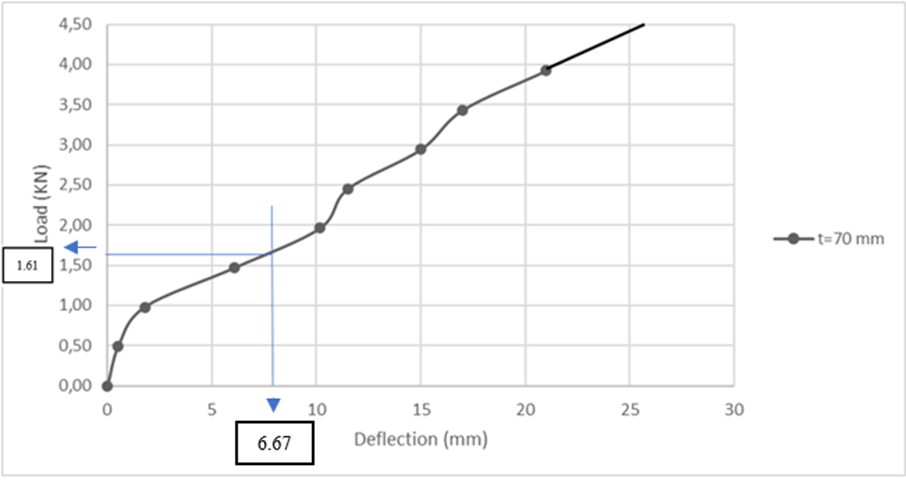
Fig. 4. Deflection Graph vs Load t = 70 mm
The Fig. 4 above illustrates the load–deflection characteristics of a specimen with a thickness of 70 mm under incremental loading conditions. The curve represents a nonlinear trend, beginning with a steep slope that gradually shifts to a more moderate increase in load as deflection advances, indicating a blend of elastic and plastic deformation mechanisms.
At a deflection of 6.67 mm, the applied load is approximately 1.61 kN, which is marginally lower than the load recorded for the specimen with a thickness of 80 mm. The observed difference suggests that a reduction in specimen thickness leads to a decline in stiffness and load-bearing capacity at comparable deflection levels.
After this deflection point, the load increases nearly linearly, reaching approximately 3.0 kN at a deflection of around 15 mm. This is then succeeded by a gentler slope leading to the peak recorded load of roughly 4.2 kN at a deflection of around 24 mm. The lack of abrupt changes or interruptions in the load path indicates that the specimen demonstrated consistent deformation without experiencing brittle fracture.
The load–deflection response exhibits a progressive nature, highlighting the material’s ability to experience considerable deformation before reaching ultimate failure. This characteristic may be advantageous for applications that require ductility and effective energy dissipation. In comparison to the thicker specimen (t = 80 mm), this configuration exhibits a marginally reduced peak load. It attains maximum deflection at a lesser value, underscoring the impact of thickness on structural stiffness and strength.
Table 6. Deflection and Load t = 75 mm
|
Thicknes |
Load (KN) |
Deflection (mm) |
|
t= 75 mm |
0.00 |
0 |
|
0.49 |
0.76 |
|
|
0.98 |
3.81 |
|
|
1.47 |
7.11 |
|
|
1.96 |
8.56 |
|
|
2.45 |
13.72 |
|
|
2.94 |
16.5 |
|
|
3.43 |
21 |
|
|
3.92 |
- |
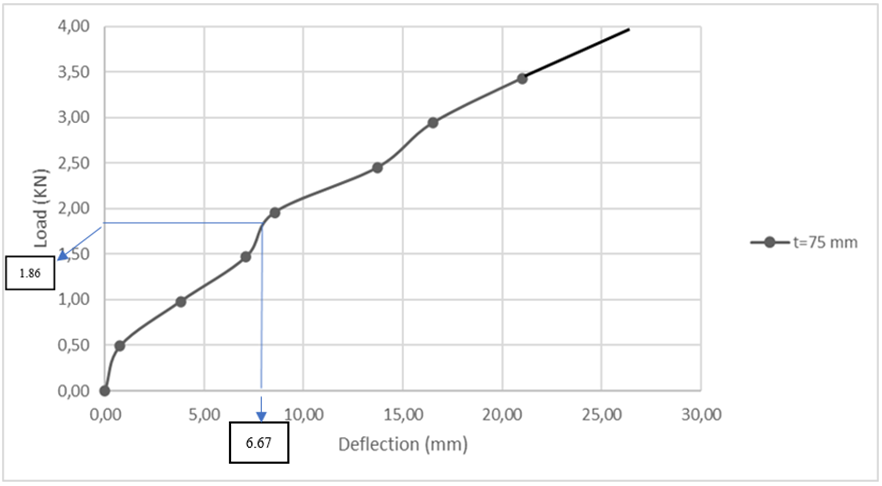
Fig. 5. Deflection Graph vs Load t = 75 mm
The Fig. 5 above indicates that the load–deflection curve for the specimen with a thickness of 75 mm exhibits a nonlinear mechanical response, characteristic of ductile materials subjected to progressive loading. The curve initiates with a notably steep slope, reflecting elastic behavior, and then transitions into a more gradual slope indicative of plastic deformation or damage accumulation.
With a deflection of 6.67 mm, the applied load attains 1.86 kN, indicating that this specimen’s initial stiffness and load capacity fall within the range of the 70 mm and 80 mm thick specimens. This observation is consistent with the hypothesis that greater specimen thickness typically corresponds to improved load-bearing capacity.
After reaching the 6.67 mm deflection point, the load increases progressively alongside the deflection, exhibiting a consistent and stable curve without any abrupt declines. The load reaches a maximum of around 3.7 kN at a deflection of nearly 25 mm, demonstrating that the specimen is capable of withstanding considerable deformation before failure occurs.
The mechanical behavior of the 75 mm thick specimen illustrates a harmonious interplay between strength and ductility. The lack of signs indicating brittle fracture, along with the ongoing increase in load, points to a positive energy absorption capacity. This configuration is therefore suitable for structural applications that require a balance of moderate stiffness, strength, and deformability.
Table 7. Deflection and Load t = 80 mm
|
Thicknes |
Load (KN) |
Deflection (mm) |
|
t= 80 mm |
0.00 |
0 |
|
0.49 |
0.38 |
|
|
0.98 |
2.03 |
|
|
1.47 |
4.88 |
|
|
1.96 |
8.64 |
|
|
2.45 |
11.18 |
|
|
2.94 |
14 |
|
|
3.43 |
16.5 |
|
|
3.92 |
20.5 |
|
|
4.41 |
28 |
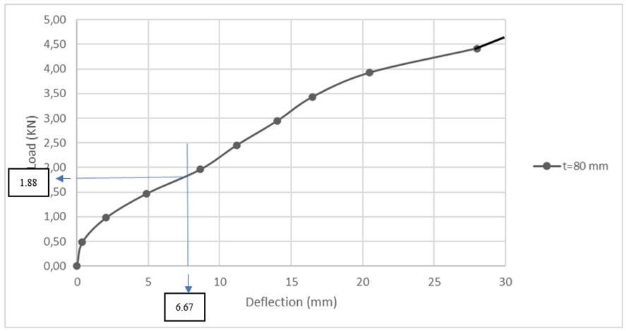
Fig. 6. Deflection Graph vs Load t = 80 mm
The Fig. 6 above illustrates the load–deflection relationship for a specimen measuring 80 mm in thickness subjected to applied loading. The curve demonstrates a nonlinear response, typical of the behavior exhibited by ductile materials when undergoing mechanical deformation. At first glance, the specimen exhibits a pronounced slope, suggesting a considerable level of stiffness. With the increase in applied load, the curve's slope diminishes, indicating a decrease in stiffness and a shift towards plastic deformation.
At a deflection of 6.67 mm, the associated load is roughly 1.88 kN, as illustrated in the graph. This point can be understood as a transition similar to yield, where the material starts to undergo more considerable deformation with a smaller proportional increase in load. Beyond this point, the material continues to endure escalating load until it attains a maximum recorded load of approximately 4.6 kN at a deflection close to 28 mm.
The gradual and uninterrupted rise in both load and deflection, devoid of abrupt declines, indicates that the specimen likely did not undergo brittle failure. The observed behavior suggests a consistent and advancing deformation process, likely influenced by mechanisms of plastic yielding or the accumulation of damage.
This behavior is especially significant for applications that necessitate energy absorption or load redistribution, as the material shows a capacity to endure considerable deformation prior to ultimate failure.
Table 8. Deflection and Load t = 90 mm
|
Thicknes |
Load (KN) |
Deflection (mm) |
|
t= 90 mm |
0.00 |
0 |
|
0.49 |
1.17 |
|
|
0.98 |
2.95 |
|
|
1.47 |
3.56 |
|
|
1.96 |
5.84 |
|
|
2.45 |
10.34 |
|
|
2.94 |
13.34 |
|
|
3.43 |
16.34 |
|
|
3.92 |
24.84 |
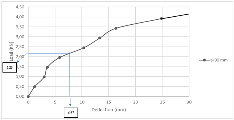
Fig. 7. Deflection Graph vs Load t = 90 mm
The Fig. 7 above indicates that load–deflection behavior of a specimen measuring 90 mm in thickness when subjected to compressive loading. The curve illustrates a nonlinear progression, characteristic of materials experiencing an elastic-to-plastic transition and ongoing strain hardening.
At a deflection of 6.67 mm, the applied load attains 2.23 kN, marking the peak value among all thicknesses examined in this analysis. This suggests that a greater specimen thickness improves both the initial stiffness and the load-bearing capacity. The initial segment of the curve displays a pronounced slope, indicating significant resistance to deformation and considerable structural rigidity.
Beyond the initial range, the curve shifts into a more gradual slope, signifying plastic deformation behavior. The load persists in its gradual ascent, attaining a peak of approximately 4.3 kN at a deflection of nearly 27 mm. The absence of sudden drops or discontinuities indicates that the failure mode is ductile and does not exhibit characteristics of brittle fracture.
The overall behavior of the 90 mm thick specimen indicates exceptional structural performance, integrating high strength with commendable deformability. This makes it especially suitable for applications that require significant energy absorption and enduring mechanical stability under load.
Table 9. Deflection and Load t = 100 mm
|
Thicknes |
Load (KN) |
Deflection (mm) |
|
t=100 mm |
0.00 |
0 |
|
0.49 |
0.13 |
|
|
0.98 |
1.02 |
|
|
1.47 |
2.79 |
|
|
1.96 |
4.57 |
|
|
2.45 |
6.25 |
|
|
2.94 |
9.4 |
|
|
3.43 |
11 |
|
|
3.92 |
14 |
|
|
4.41 |
17 |
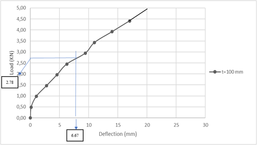
Fig. 8. Deflection Graph vs Load t = 100 mm
The Fig. 8 above indicates that the load–deflection curve for the specimen with a thickness of 100 mm exhibits a distinct nonlinear trend, indicating the progressive deformation behavior that occurs with loading. The beginning segment of the curve shows a pronounced incline, indicative of the elastic region, where the specimen displays significant stiffness and minimal deformation.
At a deflection of 6.67 mm, the specimen endures a load of around 2.78 kN, marking the peak initial response recorded among the evaluated thicknesses. This finding validates that greater thickness contributes to improved load resistance and structural stiffness during the initial stages of deformation.
Following this initial response, the curve exhibits a gradual decrease in slope, indicating a transition from elastic to plastic behavior. The load persists in its gradual ascent, culminating in a maximum of approximately 4.8 kN at a deflection of slightly less than 20 mm. The consistent and unbroken form of the curve, devoid of abrupt declines, indicates stable plastic deformation and ductile failure characteristics.
The performance of the 100 mm thick specimen highlights its exceptional mechanical capacity in terms of strength and stiffness. This configuration is ideal for structural applications that require significant load-bearing capacity and precise deformation control, especially in components that absorb energy or are critical for safety..
Table 10. Deflection and Load t = 110 mm
|
Thicknes |
Load (KN) |
Deflection (mm) |
|
t = 110 mm |
0.00 |
0 |
|
0.49 |
0.38 |
|
|
0.98 |
0.64 |
|
|
1.47 |
1.02 |
|
|
1.96 |
2.54 |
|
|
2.45 |
4.95 |
|
|
2.94 |
8.13 |
|
|
3.43 |
10 |
|
|
3.92 |
12.5 |
|
|
4.41 |
13.5 |
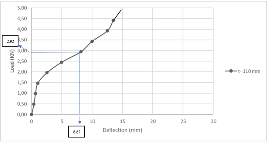
Fig. 9. Deflection Graph vs Load t = 110 mm
The Fig. 9 above indicates that the load–deflection curve for the specimen with a thickness of 110 mm exhibits a characteristic nonlinear response, illustrating the material's transition from elastic deformation to plastic behavior as the load increases. Initially, the curve shows a pronounced slope, indicating considerable stiffness and limited deformation within the elastic region.
At a deflection of 6.67 mm, the applied load attains around 2.92 kN, marking the peak load documented at this deflection among all evaluated thicknesses. This indicates that a rise in specimen thickness significantly enhances the early-stage load-bearing capacity, likely due to increased cross-sectional rigidity.
Beyond this point, the curve exhibits a steady upward trajectory, culminating in a peak load of approximately 4.6 kN at a deflection of roughly 14 mm. The deflection capacity may be lower in comparison to thinner specimens; however, the load capacity ranks among the highest, thereby validating the stiffness–ductility trade-off associated with increased thickness.
The lack of abrupt declines in the curve indicates consistent plastic deformation and a ductile failure mode. Nonetheless, the comparatively limited deflection range indicates that although thicker specimens offer enhanced strength, they might display a marginal decrease in ductility.
The performance profile of this 110 mm thick specimen positions it as an excellent choice for structural applications that demand maximum load resistance while maintaining controlled deformation, especially in scenarios where rigidity is favored over the capacity for large deflections.
Table 11. Deflection and Load t = 115 mm
|
Thicknes |
Load (KN) |
Deflection (mm) |
|
t = 115 mm |
0.00 |
0 |
|
0.49 |
0 |
|
|
0.98 |
0.25 |
|
|
1.47 |
0.38 |
|
|
1.96 |
0.64 |
|
|
2.45 |
2.79 |
|
|
2.94 |
4.7 |
|
|
3.43 |
6.1 |
|
|
3.92 |
7.11 |
|
|
4.41 |
8.38 |
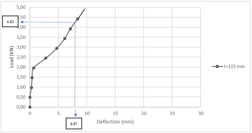
Fig. 10. Deflection Graph vs Load t = 115 mm
From the Fig. 10 above. The load–deflection curve for the 115 mm thick specimen demonstrates a notably rigid and robust structural response when subjected to applied loading. The curve exhibits a sharp ascent from the origin, signifying that the material shows a strong resistance to deformation and predominantly stays within the elastic region during the initial stages of loading.
At a deflection of 6.67 mm, the corresponding load attains roughly 4.63 kN, marking the peak load recorded at this deflection among all evaluated thicknesses. This indicates that a rise in specimen thickness results in a notable improvement in stiffness and load-bearing capacity.
The overall deflection range is notably constrained, with the curve attaining its maximum at around 9.5 mm. The pronounced increase followed by the abrupt end of the curve suggests a potential shift towards brittle or sudden failure upon achieving the peak load. In contrast to thinner specimens that exhibited broader deflection ranges, the 115 mm specimen appears to emphasize strength over ductility.
This observation suggests that although the specimen can withstand substantial loads, its ability to deform is limited. This thickness could be optimal for structural applications where it is essential to maximize load resistance and rigidity, while also minimizing or preventing large deformations.
Table 12. Deflection and Load t = 120 mm
|
Thicknes |
Load (KN) |
Deflection (mm) |
|
t = 120 mm |
0.00 |
0 |
|
0.49 |
0 |
|
|
0.98 |
0 |
|
|
1.47 |
0.25 |
|
|
1.96 |
0.3 |
|
|
2.45 |
0.64 |
|
|
2.94 |
2.41 |
|
|
3.43 |
3.94 |
|
|
3.92 |
5.21 |
|
|
4.41 |
6.22 |
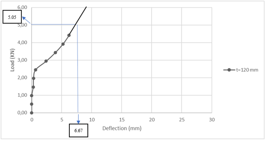
Fig. 11. Deflection Graph vs Load t = 120 mm
The Fig. 11 The load–deflection curve for the specimen with a thickness of 120 mm exhibits a notably rigid mechanical response, marked by a pronounced initial rise in load accompanied by minimal deflection. The pronounced incline observed here signifies a considerable level of structural stiffness, indicating that the specimen experiences negligible deformation within the elastic range.
At a deflection of 6.67 mm, the associated load attains 5.05 kN, marking the peak load documented at this deflection across all evaluated thicknesses. The findings indicate that a significant increase in specimen thickness enhances both the load-bearing capacity and the initial stiffness of the system.
The curve exhibits a steep ascent, indicating that the specimen is capable of withstanding even higher loads with minimal further deformation. Nonetheless, the range of deflection is notably constrained, indicating that this particular configuration prioritizes strength and rigidity rather than ductility. The steep increase and restricted lateral expansion of the curve suggest a propensity for sudden or brittle failure after reaching peak load, accompanied by minimal warning deformation.
The characteristics of the 120 mm thick specimen render it appropriate for applications that require high load-bearing capacity with minimal deformation. This is particularly relevant in structural components where it is essential to preserve shape and limit deflection, even though post-yield ductility may not be a key factor in the design process.
Table 13. Deflection and Load t = 130 mm
|
Thicknes |
Load (KN) |
Deflection (mm) |
|
t = 130mm |
0.00 |
0 |
|
0.49 |
0 |
|
|
0.98 |
0.13 |
|
|
1.47 |
0.25 |
|
|
1.96 |
0.38 |
|
|
2.45 |
1.14 |
|
|
2.94 |
1.91 |
|
|
3.43 |
2.84 |
|
|
3.92 |
3.68 |
|
|
4.41 |
4.7 |
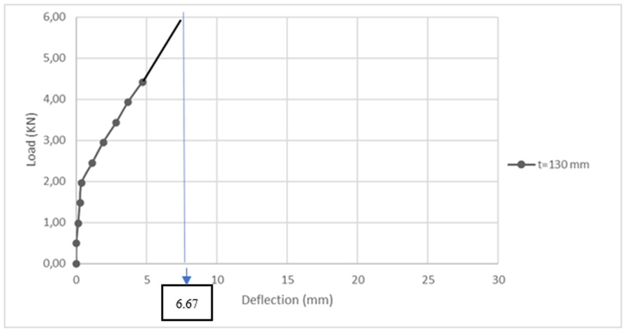
Fig. 12. Deflection Graph vs Load t = 130 mm
The Fig. 12 above indicates that the load–deflection graph for the 130 mm thick specimen exhibits a remarkably rigid mechanical response, marked by a sharp and almost linear rise in load accompanied by minimal deflection. This demonstrates a notably inflexible structural performance, wherein the material effectively withstands deformation when subjected to applied loads.
At a deflection of 6.67 mm, the load has surpassed 5.0 kN, marking it as the highest initial load response recorded among all tested thicknesses. The ongoing upward trend indicates that the specimen maintains considerable strength beyond this juncture. However, the complete peak load and post-yield behavior are not entirely represented within the existing deflection range.
The steep inclination of the curve emphasizes a material characteristic that emphasizes optimal stiffness and strength, with minimal ductility present. The absence of curve flattening or plateauing indicates that the specimen could be susceptible to sudden or brittle failure if the loading persists beyond the elastic region.
The performance of the 130 mm specimen indicates its suitability for structural elements that require high load-bearing capacity and minimal deformation, particularly in compression-dominated components or protective barriers. Nonetheless, the restricted ability to deform could pose challenges in scenarios that necessitate energy absorption or provide failure indications via significant deformations.
1.1 Recapitulation
The allowable flexural strength and permissible deflection results as a consequence of the 9 variations of precast CLC Slab panels above are as follows:
Table 14. Flexural Strength of Precast CLC Slab Panels Recapitulation
|
No |
Variation |
Maximum Flexure Test (mm) |
Live Load on Slab panel (KN) |
Live Load Minimum (KN) |
|
1 |
t=70 |
6.67 |
1.61 |
2.5 |
|
2 |
t=75 |
6.67 |
1.86 |
2.5 |
|
3 |
t=80 |
6.67 |
1.88 |
2.5 |
|
4 |
t=90 |
6.67 |
2.23 |
2.5 |
|
5 |
t=100 |
6.67 |
2.78 |
2.5 |
| 6 |
t=110 |
6.67 |
2.92 |
2.5 |
|
7 |
t=115 |
6.67 |
4.63 |
2.5 |
|
8 |
t=120 |
6.67 |
5.05 |
2.5 |
|
9 |
t=130 |
6.67 |
6.00 |
2.5 |
The maximum deflection from the 6.67 mm (L/24) to live load minimum requirement can be represented as a graph based on the thickness of the precast CLC Slab panels, as shown in table 14. The point from which the fig. 13 below was generated:
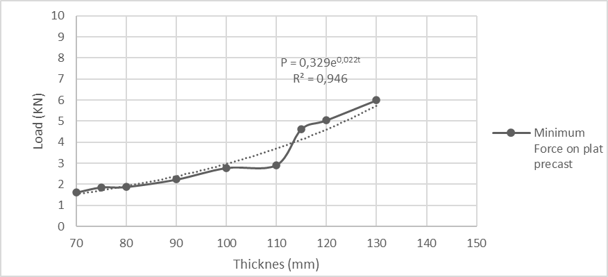
Fig. 13. Thickness of Graphics vs Slab Precast Minimum Load
Based on the graph above. the minimum load that can be accommodated by the thickness of the CLC precast slab is represented by P = 0.329e0.022t, with an R2 value of 0.946. For this reason, the graph's confidence level is satisfactory. By employing the equation provided, it is possible to determine the minimum force that the CLC precast slab can withstand in order to determine the thickness requirement. The observed nonlinear behavior can be attributed to the synergistic effects of a larger cross-sectional area and enhanced confinement, both of which contribute to the specimen's ability to withstand deformation when subjected to external loads. The exponential fit indicates that the advantages of enhanced thickness become increasingly pronounced at elevated levels, while yielding diminishing returns at the lower spectrum.
Overall, this analysis confirms that plate thickness is a critical design parameter in precast systems, significantly influencing their load-bearing capacity. The derived equation serves as a valuable predictive tool for preliminary design, enabling engineers to estimate the minimum load resistance for specified thicknesses.
4 Conclusions
This study provides strong evidence that optimizing the thickness of Cellular Lightweight Concrete (CLC) panels represents a significant breakthrough in sustainable construction technology, especially for challenging geotechnical conditions. Through rigorous experimental testing of nine panel specimens, the study conclusively establishes that 100 mm is the critical threshold thickness that successfully balances structural performance with environmental responsibility meeting the 2.5 kN live load requirement over a 1.600 mm span while meeting maximum deflection criteria. The developed mathematical relationship P= 0.329e0.022t provides a powerful predictive tool that converts qualitative production knowledge into precise engineering parameters, allowing engineers to optimize panel dimensions for specific applications. These CLC panels demonstrate tremendous potential to reduce embodied carbon because reduce cement, minimize material consumption, and reduce structural loads throughout the building system. This study goes beyond theoretical significance by providing an easily applicable solution for construction in challenging soils such as peatlands in West Kalimantan, Indonesia, where lightweight materials are critical for structural stability. By establishing a quantitative relationship between panel thickness, and the load capacity of a structure to improve performance, as well as environmental impact, this study advances sustainable materials science and the practical application of lightweight concrete slab panel technology in industrial construction.
Acknowledgements
Thank you to the Faculty of Engineering at Tanjungpura University for providing the funding for this research.
References
- S. N. Elkabany. A. El-Kordy. and H. Sobh. “Optimization of the Panels Used in Free-Form Buildings and Its Impact on Building Cost.” in IOP Conference Series Materials Science and Engineering. IOP Publishing. Dec. 2020. p. 12010. doi: 10.1088/1757-899x/974/1/012010.
- Badan Standarisasi Nasional. SNI C597:2012 Tata Cara Pemilihan Campuran Beton Normal. Beton Berat Dan Beton Massa. Jakarta: Departemen Pekerjaan Umum. 2012.
- K. Lin. Y. Z. Totoev. H. Liu. and T. Guo. “In-Plane Behaviour of a Reinforcement Concrete Frame with a Dry Stack Masonry Panel.” Materials. vol. 9. no. 2. p. 108. Feb. 2016. doi: 10.3390/ma9020108.
- S. S. Abdulhussein, E. K. Jaafar, and M. S. Rasheed, “THE FLEXURAL BEHAVIOR OF SUSTAINABLE LIGHTWEIGHT CONCRETE HOLLOW CORE SLABS,” Journal of Applied Engineering Science, Mar. 2024, doi: 10.5937/jaes0-47131.
- A. H. Salih, H. D. Hussain, A. A. G. Abu Altemen, and N. Z. Jameel, “AN EXPERIMENTAL INVESTIGATION OF THE OPTIMUM REPLACEMENT RATIO OF COARSE GRAVEL WITH EXPANDED POLYSTYRENE BEADS IN CONCRETE,” Journal of Applied Engineering Science, Jan. 2023, doi: 10.5937/jaes0-39842
- W. Huang. X. Ma. B. Luo. Z. Li. and Y. Sun. “Experimental Study on Flexural Behaviour of Lightweight Multi-Ribbed Composite Slabs.” Advances in Civil Engineering. vol. 2019. no. 1. Jan. 2019. doi: 10.1155/2019/1093074.
- D. Jain. A. K. Hindoriya. and S. S. Bhadauria. “Evaluation of properties of cellular light weight concrete.” AIP conference proceedings. vol. 2158. p. 20034. Jan. 2019. doi: 10.1063/1.5127158.
- L. Guo and H. W. Song. “Analysis of Energy-Saving Architecture with Self Thermal Insulation Structure of Fiber Reinforced Foamed Concrete.” Applied Mechanics and Materials. p. 444. Jul. 2011. doi: 10.4028/www.scientific.net/amm.71-78.444.
- E. Sutandar. A. Supriyadi. and C. P. Andalan. “Effect of Cement Variation on Properties of CLC Concrete Masonry Brick.” MATEC Web of Conferences. vol. 159. p. 1008. Jan. 2018. doi: 10.1051/matecconf/201815901008.
- SNI 03-1974-1990. "Metode Pengujian Kuat Tekan Beton." Badan Standarisasi Nasional. Jakarta: Departemen Pekerjaan Umum. 1990.
- Badan Standarisasi Nasional. SNI 2847-2019 Persyaratan Beton Struktural Untuk Bangunan Gedung. Jakarta: Departemen Pekerjaan Umum. 2019.
- S. Šupić, B. Poletanović, V. Radonjanin, M. Malešev, I. Merta, and V. Pantić, “INFLUENCE OF ACCELERATED AGEING ON PULL-OFF STRENGTH OF CONCRETE PRODUCED WITH RECYCLED CONCRETE AGGREGATE AND BLENDED WITH HEMP FIBERS,” Journal of Applied Engineering Science, Jan. 2024, doi: 10.5937/jaes0-50466
- Badan Standarisasi Nasional. SNI 1727-2020 Beban desain minimum dan kriteria terkait untuk bangunan gedung dan struktur lain. Jakarta: Departemen Pekerjaan Umum. 2020
- Badan Standarisasi Nasional. "Metode Pengujian Berat Jenis Semen Portland." SNI 15-2531-1991. Jakarta: Departemen Pekerjaan Umum. 1991.
- Badan Standarisasi Nasional. Spesifikasi Agregat Halus Untuk Pekerjaan Adukan Dan Plesteran Dengan Bahan Dasar Semen. SNI 03-6820-2002. 2002.
- Badan Standarisasi Nasional. SNI 2049:2015 Semen Portland. Jakarta: Departemen Pekerjaan Umum. 2015.
- T. Mulyono. Teknologi Beton. Yogyakarta: Andi. 2004.
- Tjokrodimuljo. Teknologi Beton. Yogyakarta: Biro Penerbit. 2007.
- R. Sepriawan. "Soil Characteristics in Kalimantan Island for Construction." 2014..
- D.Salim. D.. Sutandar. E.. Supriyadi. A (2023). Experimental Study Of The Effect Of Coarse Aggregate Fine Modulus (MHB) On The Physical And Mechanical Properties Of Pervious Concrete. IJAEM 3. Issn 2395-5252. Volume 5. Issue 11.
- Wijaya. E.. Sutandar. E.. Aryanto (2023). The Effect of Foam Agent’s Viscocity to Cellular Lightweight Concrete Brick’s Physics and Mechanics Property. International Journal of Advances in Engineering and Management (IJAEM). Volume 5. Issue 11. Nov. pp : 122:127.
- E. Sutandar. A. Supriyadi. G. Setyabudi. C. P. Handalan. dan M. Indrayadi. "Effect of Sand Gradient Variation on Properties of CLC Concrete Mansory Brick." The International Journal of Engineering and Science (IJES). vol. 10. no. 3. pp. 13–21. 2021.
- B. R. Kharel dan S. Maharjan. "Variation Analysis of Compressive Strength and Dry Density of Cellular Lightweight Concrete (CLC) Brick with Replacement of Sand by Fly Ash." Proceedings of IOE Graduate Conference. vol. 6. pp. xx–xx. May 2019.
- Sutandar. E. (2025). Pengaruh Berat Volume terhadap Sifat Fisis dan Mekanis Bata Ringan CLC . Jurnal Komposit: Jurnal Ilmu-Ilmu Teknik Sipil . 9(1). 63–71. https://doi.org/10.32832/komposit.v9i1.16393.
- R. Hardianto. E. Sutandar. dan A. Supriyadi. “Studi eksperimental pembuatan bata ringan foam agent (busa) dengan variasi pemakaian air.” JeLAST: Jurnal Teknik Kelautan. PWK. Sipil. dan Tambang. vol. 5. no. 1. 2018. [Online]. Tersedia: https://jurnal.untan.ac.id/index.php/JMHMS/article/view/23914
- K. K. B. Siram. "Cellular light-weight concrete blocks as a replacement of burnt clay bricks." Int. J. Eng. Adv. Technol. (IJEAT). vol. 2. no. 2. 2012. [Online]. Available: https://www.ijeat.org/portfolio-item/b0887112212/
- W. A. P. Putra. "Comparison of compressive strength and tensile stress brick lightweight concrete with the addition of natural mineral zeolite sieve retained no. 80 (0.180 mm) and held by sieve No. 200 (0.075 mm)." S.T. thesis. Technical University of Brawijaya. 2015. [Online]. Available: https://www.google.co.id/books/edition/Teknologi_Beton/4ZZaEAAAQBAJ?hl=id&gbpv=1&dq=%E2%80%9CTeknologi+Beton%E2%80%9D.+Penerbit+ANDI.+Yogyakarta&pg=PT63&printsec=frontcover
- E. Sutandar. A. Supriyadi. dan J. Ferry. "Effect of mineral admixture on physical and mechanical properties of CLC concrete masonry brick." International Journal of Scientific Advances. vol. 3. no. 1. 2022. [Online]. Available: https://www.ijscia.com/wp-content/uploads/2022/01/Volume3-Issue1-Jan-Feb-No.216-62-65.pdf
Conflict of Interest Statement
The authors declare that there is no conflict of interest in this research.
Author Contributions
Data Availability Statement
The data presented in this research are available in the article.
Supplementary Materials
There are no supplementary materials to include.