Volume 23 article 1305 pages: 706-714
Received: Jun 09, 2025 Accepted: Dec 01, 2025 Available Online: Dec 13, 2025 Published: Dec 15, 2025
DOI: 10.5937/jaes0-59381
ANALYSIS OF CYLINDER HEAD REPAIR OF MAIN ENGINE: A CASE STUDY OF PASSENGER SHIP KM GD IN INDONESIA
Abstract
KM GD a passenger ship operated by PT. PELNI. Playing an important role as a transportation link between regions in Indonesia, especially given the country’s archipelagic geography. The reliability of the main engine as the main driver of the ship is a crucial factor in ensuring smooth operations. One of the vital components in a master engine system is the cylinder head at KM GD was found to have repeated damage to the cylinder head shortly, although repairs have been made. Damage to the cylinder head has a high presentation on engine operation. Repeated damage is interesting for research to discover more details about the causes of cylinder head cracks. This study identified the root cause of damage using the Root Cause Analysis method with the 5 Whys approach and the Fishbone diagram. The results of the study show that many factors are the cause of cracks. The main factor of damage is a non-standard reconditioning procedure. Repairs to standards provide significant savings and improve engine reliability. Research using the RCA method effectively analyses technical issues and supports efficient and sustainable treatment decision-making. Recommendations are given to improve the working performance of the machine after reconditioning, among others, through the implementation of strict technical procedures according to the manufacturer's standards and increased quality control during the repair process. With a thorough improvement in this technical and managerial aspect, it is hoped that the damage frequency can be reduced and the reliability of the main's engine can be optimally maintained to support operations KM GD.
Highlights
- Root Cause Analysis reveals that non-standard procedures are the main cause of cylinder head cracks.
- Inadequate reconditioning practices accelerate recurrence of component failure.
- Integrating RCA with Fishbone and 5 Whys enhances maintenance reliability.
- Results support optimization of the Planned Maintenance System for marine engines.
Keywords
Content
1 Introduction
The main engine is the core propulsion system of a ship that drives the propellers, enabling navigation between ports. It consists of various key components, such as cylinder blocks, pistons, and connecting rods [1][ with the cylinder head being one of the most critical. The cylinder head closes the combustion chamber and ensures optimal combustion performance. It also houses the valve system, spark plug mounts, connections for inlet and exhaust manifolds, and water jackets for cooling [2]. Because it operates under extreme temperature and pressure, the cylinder head must be made from durable materials such as cast iron, known for its high strength and resistance to harsh conditions.[3] Functionally, the cylinder head forms the upper boundary of the combustion chamber and is firmly fastened to the cylinder block using high-tension bolts to maintain a sealed environment during combustion.[4] Given its crucial function, the cylinder head requires systematic maintenance to prevent damage that could disrupt overall engine performance. [5]
Maintenance that is not performed regularly can lead to unplanned downtime, thereby reducing the operational efficiency of the vessel. To mitigate this, a schedule-based maintenance approach, such as the Planned Maintenance System (PMS), is implemented [6]. PMS facilitates early detection of potential component failures, including those involving the cylinder head, thus ensuring greater operational reliability. Additionally, supporting subsystems such as the cooling and lubrication systems must function optimally to maintain stable engine temperatures and minimize frictional wear. [7]. The effectiveness of the PMS, however, depends not only on adherence to maintenance schedules but also on the quality and consistency of its database configuration. According to Stazić et al [8], the absence of standardized methodologies in evaluating PMS databases can result in subjectivity and inconsistencies in maintenance decision-making. Their research highlights that systematic evaluation of PMS data improves reliability, reduces human error, and enhances the accuracy of maintenance planning. This underscores the importance of adopting data driven and analytical approaches such as Root Cause Analysis (RCA) to improve the reliability of marine engine maintenance systems.[9]. [10].
One analytical method widely used across industrial sectors to address technical problems is the Root Cause Analysis (RCA) method [11], [12]. The RCA method is widely used in various industries to analyse sources, such as RCA analysis of work accidents, quality improvement, and information. [6], [7], [11]. However, the application of RCA in the maritime industry, which has great potential, especially in the machinery field, is still minimal in exploration. Using other methods, such as FMEA, also makes it possible to analyse risk severity and help to make the process more structured [13] Alternatively, the RCM method can be used. But to find the source and overcome the problem, it is necessary to do it with the RCA method [14], [15]. Root Cause Analysis (RCA) Method In the scope of ship engine maintenance, especially in the analysis of cylinder head cracks, RCA combines the 5 Whys and Fishbone Diagram techniques to map the contribution of technical factors (over-heating, over-compression pressure), procedural factors (reconditioning that does not follow standards), operational factors (shipping schedule pressure), and materials factors (metal wear and fatigue). This layered approach allows researchers to comprehensively trace the cause-and-effect pathway so that its corrective actions are on target and sustainable. Consistent implementation of RCA has been proven to reduce the frequency of recurrent failures, increase the effectiveness of the Planned Maintenance System (PMS) program, and result in significant operational cost savings through extended service life of critical components such as cylinder heads. The Root Cause Analysis (RCA) method is a structured analytical approach that aims to uncover the root cause of a failure rather than simply mitigate its symptoms [11]. A practical analysis (RCA) of cylinder head damage should be carried out systematically to find the leading cause, such as poor lubrication, oil leakage, or vibration. This approach is more than just replacing damaged components, as the primary focus is on preventing future damage from happening again.[16]
In the scope of ship engine maintenance, especially in the analysis of cylinder head cracks, RCA combines the 5 Whys and Fishbone Diagram techniques to map the contribution of technical factors (over-heating, over-compression pressure), procedural factors (reconditioning that does not follow standards), operational factors (sailing schedule pressure), and material factors (metal wear and fatigue). This layered approach allows researchers to comprehensively trace the cause-and-effect pathway so that its corrective actions are on target and sustainable. Consistent implementation of RCA has been proven to reduce the frequency of recurrent failures, increase the effectiveness of the Planned Maintenance System (PMS) program, and result in significant operational cost savings through extended service life of critical components such as cylinder heads.
The case of damage that occurred at KM GD is an important background for this research. Within 6 months, there was a recurring crack in the cylinder head of the main engine even though maintenance and replacement had been carried out. This condition poses a potential disruption to ship operations and increases the risk of losses due to long repair times and limited spare parts. Therefore, this study analysed the root cause of cylinder head damage using the RCA approach to provide recommendations for improving procedures and the overall effectiveness of engine maintenance.
2 Materials and methods
Root Cause Analysis is a research technique that aims to identify the fundamental cause of a problem and provide the most effective solution to prevent its recurrence. In this study, the process of identifying the cylinder head cracks on KM GD involves several key contributing factors from both technical and procedural perspectives. The steps of the RCA process used to determine the root cause of the cylinder head damage are as follows:
1) A literature review examined relevant theories regarding cylinder heads, cracks, and RCA methods. RCA is a systematic approach to identifying the root cause of a problem [11], using techniques such as the 5 Whys and the Fishbone diagram
2) Engine data was collected through a Primary Data Field Survey, observation of damage conditions, and interviews with PT. PELNI (Persero) and technicians. Questionnaires were also distributed to four technical personnel. Then, the secondary data of the KM GD manual book will be presented. KM GD historical damage data (FPP), PMS data, maintenance procedure data, fuel system data, cylinder head service life data, and cooling system data.
3) The collected data were analysed using the Root Cause Analysis (RCA) method, following the structured stages illustrated in Figure 1 (Research Flowchart). The analysis process focused on identifying interrelated causal factors and validating them through the 5 Whys and Fishbone techniques to determine the most probable root cause of the cylinder head cracking.
4) To enhance the accuracy and prioritization of root cause identification, the Failure Mode and Effect Analysis (FMEA) concept was integrated as a supporting assessment step. The FMEA method evaluates each potential failure mode by considering its Severity (S), Occurrence (O), and Detection (D), which together form the Risk Priority Number (RPN). This allows the ranking of the most critical failures affecting the cylinder head system.
FMEA can be further expanded into a Failure Modes, Effects, and Risks Analysis (FMERA) framework, which not only assesses the probability of failure but also quantifies the economic consequences such as downtime and maintenance costs. This combined RCA–FMEA approach provides both qualitative and quantitative perspectives for determining the most effective corrective actions. [17].

Fig. 1. Flowchart
To enhance the reliability of RCA results, this study integrates the FMEA as a complementary method. FMEA identifies potential failure modes and ranks them using the Risk Priority Number (RPN), derived from Severity (S), Occurrence (O), and Detection (D) factors. This quantitative approach helps prioritize critical risks and supports RCA with a more structured and preventive perspective. FMEA has been widely applied in marine engineering to assess system reliability, optimize maintenance planning, and minimize operational risks. [13].
The integration of RCA and FMEA ensures a balanced qualitative and quantitative assessment, improving diagnostic accuracy and maintenance effectiveness in preventing the recurrence of cylinder head failures.
2.1 Case Study
The cylinder head is one of the components in the main ship's engine, which functions as a cover from the top of the cylinder; the cylinder is a place where it moves up and down to convert combustion energy into mechanical movement. Cracking due to thermal fatigue is one of the most common modes of damage, especially in the area of the cooling water jacket. The narrow section between the valve and the exhaust valve seat is particularly susceptible to this type of cracking due to the extreme temperature differences that occur in the region. [18]
In the context of maintenance, risks to cylinder head cracks that have undergone the reconditioning process are identified by analysing historical damage data. One of the primary sources of such data is the Repair Request Form (FPP) report, which is routinely sent from the ship to the land management. Through FPP analysis, it can be identified that patterns of repeated damage, the effectiveness of previous repairs, and potential component failures need further evaluation to support risk-based decision-making.
3 Results and discussion
In the discussion and processing of data obtained in the field. Data obtained during 2 months of industry internship.
3.1 Observation and Secondary Data
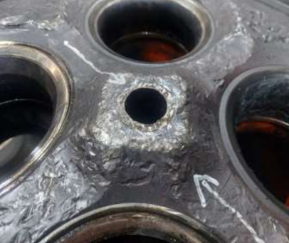
Observations based on the Repair Assessment Form (FPP) report showed repeated cracks in the cylinder head. KM GD especially in the area of the combustion chamber.
 |
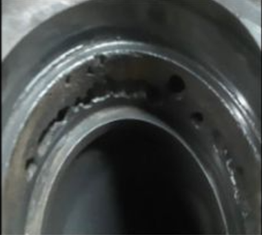 |
Fig. 2. of the cylinder head crack
Damage symptoms include oil leakage, white smoke, decreased water pressure, unusual sounds in the cylinder, high temperature, and water discharge from the indicator. PMS data (Table 1) shows the treatment schedule that has been carried out for the cylinder head based on the manual book, but the damage to the cylinder head after reconditioning still occurs, so the researcher searches more deeply using the five whys method and fishbone diagram.
Table 1. Planned maintanance system (PMS)
|
Interval [hours] |
Component |
Work/Duty |
|
150 |
Cylinder Head |
Inspection/Checking |
|
1500 |
Inlet & Exhaust Valve |
Valve Gap Inspection & Adjustment |
|
7500 |
Inlet & Outlet Valve Cones |
Inspection/Disassembly & Reassembly |
|
15000 |
Inlet & Exhaust Valve Cones |
Inspection/Disassembly & Reassembly |
|
30000 |
Valve Guide |
Inspection & Replacement |
|
Cylinder Head |
Maintenance & Cleaning |
|
|
Relief Valves |
Maintenance & Replacement |
|
|
Valves Rockers |
Maintenance/Disassembly & Reinstallation |
With the presence of PMS in Table 1. the author knows that the maintenance results are by factory standards, so the author continues the analysis to the next stage.
3.2 Interviews and Questionnaires
Based on risk identification, a questionnaire was prepared to determine the general cause of cylinder head cracks from the beginning of the damage sign to the maintenance practice process. Questions 4 of the interviewees were used as a summary by including the RCA category, which can be seen in Table 1a Summary Results of the cylinder head crack questionnaire.
Table 1a. Summary of cylinder head damage questionnaire results
| No. | Question | Summary of Answers | Category: RCA | Key Themes |
| 1. | The first sign of damage? | Oil leaks, white smoke, high temperatures, strange noises, loss of power | Machine | Overheating, leakage, abnormal noise |
| 2. | Most frequent breakdowns? | Cracks, oil & water leaks, valve wear | Material | Cracks, wear, leaky gaskets |
| 3. | Common causes? | Poor cooling, AT deadlock, lifetime, raft fault | Method/Material | Cooling failure, installation error |
| 4. | How to cope? | Routine maintenance, circulation check, original parts, expert technicians | Method | Preventive care |
| 5. | Cause of time/operation? | A combination of wear, cooling, human error | Human/Material | Wear, human error |
| 6. | Improvement steps? | Disassembly, replacement, welding, pressure/leak test | Time/Method | Prosedur, overhaul |
| 7. | Repair time? | Varied (2 hours - 1 month) | Method | Variatif |
| 8. | Treatment practices? | According to the SOP, check the valve, treat the coolant, oil, | Method | Scheduled preventive care |
3.3 The results of the analysis 5 whys
The results of the root of the problem analysis using the 5 Whys Analysis method which was developed in nine stages, it can be concluded that cracks in the cylinder head are not solely caused by material fatigue, but are the result of a series of interrelated systemic factors, including technical and managerial aspects. The dominant factor that triggers cracks is the use of cylinder heads that have exceeded the service life limit. The decision to continue using these components was based on the limited availability of new parts, considering that replacement parts were not available in ready stock and required time for the fabrication process. This condition encourages the implementation of reconditioning of cylinder heads that have previously suffered repeated damage. However, the reconditioning process was not carried out optimally and did not meet the necessary technical standards, increasing the potential for re-failure of the same components.
Table 2. Question stages "5 Whys"
| Tahap | Pertanyaan "whys" | Jawaban |
| Why 1 | Why does the cylinder head crack? | The occurrence of structural weaknesses. |
| Why 2 | Why is there structural weakness in the cylinder head? | It has passed the service life limit. |
| Why 3 | Why are you still using a cylinder head that has passed the age limit? | Since the procurement process of a new cylinder head requires a considerable aKt of time, an alternative solution was applied by repairing and maintaining the existing cylinder head. |
| Why 4 | Why does it take so long to buy spare parts? | Since the procurement of new spare parts requires prior fabrication due to the absence of ready stock, the reconditioned cylinder head was continuously used, which consequently led to repeated failures. |
| Why 5 | Why does a cylinder head that is long after reconditioning often suffer from repeated damage? | The installation of the bush is not perfect. |
| Why 6 | Why is the bush installation not perfect? | The Loctite has not dried to the maximum when installed. |
| Why 7 | Why has Loctite not dried to the maximum? | Drying time is not enough. |
| Why 8 | Why is the drying time not given long enough? | Pursue operational needs. |
| Why 9 | Why are technicians in a hurry to recondition and install? | Due to the absence of strict procedural control and the pressure from operational management to expedite the completion of the work. |
The results of the 5 Why analysis was then cross-checked using the RCA framework to ensure that each answer corresponded to the real operational condition. Factors such as inadequate cooling, excessive compression, and procedural errors in reconditioning were confirmed to have a cumulative effect leading to cracks in the cylinder head.
3.4 Fishbone Diagram
Based on the Root Cause Analysis of the cylinder head crack in the main engine KM GD, which uses a 5 Whys approach to nine stages, is damaged not only by material fatigue but also by a combination of technical, managerial, and procedural factors. To clarify the relationship between these causes, the analysis results are visualized in the Fishbone Diagram (cause-effect diagram), which groups the main factors into six categories: Human, Machine, Method, Material, Environment, and Measurement, as shown in Table 3.
Table 3. Causative factors categories
| Kategori | Detail penyebab |
| Human | - Technicians lack discipline waiting for loctice drying time |
| Machine | - Machines are directly used with high operating loads |
| Method | - The tightness test process was carried out not in accordance with MAK standards, the cylinder head was only tested at 10 bar with a short time and the temperature did not reach 80 degrees Celsius |
| Material | - Loctice has not dried out to the maximum - The use of adhesive material is not suitable for drying procedures |
| Environment | - The temperature of the workshop room is too low |
| Measurement | - Operational pressure to accelerate deployment - No refurbishment quality control system |
With the data obtained in the five why interview, it can be concluded through grouping as in (table 3) and found fishbone diagrams such as Figure 1 Fishbone Diagram Crack cylinder head
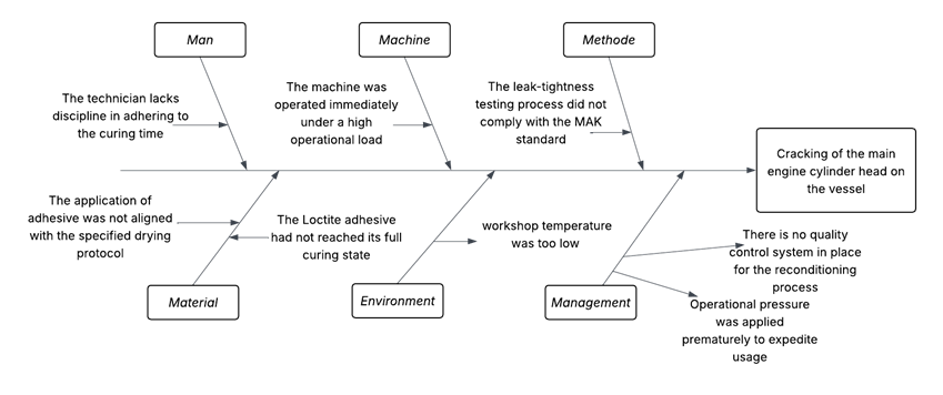
Fig. 3. Fishbone crack diagram
Using the RCA method, several factors were found that cause cracking; here are the most likely factors.
1) Overheating is generated when the cooling system is not working optimally; the engine's temperature increases to the extreme. The uneven expansion of the metal due to excessive heat causes thermal stress that triggers cracks.
2) Excessive Compression Pressure: Compression pressure that exceeds the tolerance limit is caused by fuel injection timing errors, imperfect combustion quality, or carbon deposits in the combustion chamber. Too high a pressure puts an excess load on the cylinder head structure, which in the long run can cause cracking, especially in the area around the valve seat and injector.
3) Material Fatigue occurs due to using components over a long period and continuously experiences high pressure and temperature cycles. This accumulation of cyclic stress leads to a decrease in the durability of metal structures. At some point, the strength of the metal decreases to the point where it can no longer withstand typical workloads and eventually gives rise to micro-cracks that develop into structural cracks.
4) Improper Reconditioning Procedure Reconditioning procedures that do not comply with technical standards are one of the significant factors that cause cracks. Some common findings in the field include over-welding of pocket valves, inconsistencies in the pressure test process, and neglected chemical cleaning processes. This mismatch causes the cylinder head to not return to the manufacturer's standard condition and becomes susceptible to stress when the engine returns to operation. This shows the importance of standardization and quality control in the reconditioning process.
The RCA findings were integrated back into both the 5 Why and Fishbone analyses to verify how each identified factor—cooling system inefficiency, excessive compression pressure, improper reconditioning, and material fatigue—contributed to the root cause of cylinder head cracks. This step ensured that the results of each analytical method were not treated separately, but rather complemented one another to identify the underlying technical and procedural weaknesses.
In the Fishbone Diagram analysis, cooling system factors were conceptually represented under the “Machine” and “Environment” categories. Issues such as coolant flow restriction, temperature imbalance, and insufficient circulation were identified as contributing elements that directly cause overheating and thermal fatigue leading to cylinder head cracking. Although no structural modification was made to the diagram, the inclusion of these aspects provides a clearer understanding of how cooling performance interacts with other operational variables.
The combination of RCA, 5 Why, and Fishbone methods has proven effective in tracing the problem systematically. The 5 Why method identified the sequential causes, the Fishbone diagram visualized interrelated contributing factors, and RCA synthesized these findings to determine the fundamental causes rather than surface-level symptoms. This integrated analytical approach strengthened the diagnostic accuracy and supported the development of targeted recommendations for maintenance improvement.
4 Conclusions
Based on the results of this study using the Root Cause Analysis (RCA) method, it can be concluded that the repeated damage to the cylinder head components of the main engine on KM GD was mainly caused by discrepancies in the reconditioning procedure. In particular, the imperfect drying process of adhesive materials and the implementation of pressure tests that did not comply with the manufacturer’s technical standards were identified as crucial factors that accelerated the reoccurrence of cracks after the components were used.
In addition, the results of the 5 Whys approach extended to nine stages and visualized through the Fishbone Diagram show that the damage is not a single result of material fatigue but rather a combination of interrelated technical, procedural, operational, and managerial causes. The RCA method has proven to be effective in systematically tracing the root of the problem. This approach thoroughly identifies causative factors such as overheating due to cooling system failure, excess compressive pressure arising from imperfect combustion, material fatigue due to repetitive duty cycles, and procedural errors in the reconditioning process. If not handled properly, all of these factors will continue to trigger similar failures in the future, which not only impacts engine performance but also imposes a significant burden on maintenance costs.
As a recommendation, increased supervision is needed in implementing reconditioning procedures, including adhesive quality control, pressure tests according to manufacturer's specifications, and technician training to improve technical competence and awareness of the importance of standard procedures. In addition, consistent implementation of the Planned Maintenance System (PMS) program, using original parts, and evaluating spare parts procurement management are also important steps to prevent repeated breakdowns.
By feeding the RCA findings back into the 5 Why and Fishbone analyses, this study successfully linked the observed symptoms—such as overheating, excessive compression, and repeated cracks—to systemic weaknesses within the reconditioning and cooling processes. The findings confirmed that non-standard reconditioning procedures, particularly in adhesive drying and pressure testing, remain the dominant root cause.
This research concludes that the combination of RCA, 5 Why, and Fishbone methods provides a structured and comprehensive understanding of the root causes of cylinder head damage. The integration of cooling and compression factors supports the conclusion that the failure mechanism is systemic rather than isolated.
Further research can be developed to quantitatively simulate thermal stress in relation to cooling system performance as a continuation of this study’s findings. With thorough improvements to the maintenance and reconditioning systems, it is expected that the reliability of the main engine can be significantly enhanced.
Acknowledgements
Thank you to PT. Pelni Indonesia for the cooperation and collaboration.
References
- Ulty Desi, (2021), “Komponen Mesin Diesel Kapal,” LANCANGKUNING.com, pp. 1–9.
- A. B. Geleto, (2024), “Design and Development of Combined Mechanical and Pneumatic Valve Spring Remover,” International Journal of Research Sciene and Engineering., no. 45, pp. 14–34, doi: 10.55529/ijrise.45.14.34.
- B. C. Tjiptady, R. Z. Rahman, R. F. Meditama, and G. Widayana, (2021), “Jig and Fixture Redesign for Making Reamer on Head Cylinder,” Jurnal Pendidikan Teknik Mesin Undiksha, vol. 9, no. 1, pp. 32–41, doi: 10.23887/jptm.v9i1.32597.
- Y. He, Z. He, L. Wang, and C. Gu, (2015), “Reliability Modeling and Optimization Strategy for Manufacturing System Based on RQR Chain,” Mathematical Problems in Engineering., vol. 2015, doi: 10.1155/2015/379098.
- R. Muhammad, (2024), “Analisis penyebab keretakan keberangkatan kapal di Taboneo Anchorage Banjarmasin,” Scientica Jurnal Ilmiah Sain dan Teknologi., vol. 3, no. 3021–8209, pp. 218–250.
- S. S. Islam, (2020), “Analisis Preventive Maintenance Pada Mesin Produksi dengan Metode Fuzzy FMEA,” JTT (Jurnal Teknologi Terpadu), vol. 8, no. 1, pp. 13–20, doi: 10.32487/jtt.v8i1.766.
- Agustafarman, (2023) “Upaya Mencegah Keretakan Kepala Silinder pada Mesin Induk untuk Menunjang Kelancaran Pengoperasian di AHT OPS Astrid,” Kementrian Perhubungan Badan pengembangan SDM.
- L. Stazić, T. Stanivuk, and V. Mihanović, (2019), “Testing of the evaluation methodology for ship’s planned maintenance system database,” Journal of Applied Engineering Science, vol. 17, no. 3, pp. 273–279, doi: 10.5937/jaes17-22652.
- A. T. Ofoedu, J. E. Ozor, O. Sofoluwe, and D. D. Jambol, (2022), “A Root Cause Analytics Model for Diagnosing Offshore Process Failures Using Live Operational Data,” Shodhshauryam, International Scientific Refereed Research Journal., vol. 5, no. 4, pp. 226–244.
- A. Kuswardana, N. Eka, and H. Natsir, (2017), “Analisis Penyebab Kecelakaan Kerja Menggunakan Metode RCA ( Fishbone Diagram Method And 5 – Why Analysis ) di PT . PAL Indonesia (Analysis of The Causes of Work Accidents Using the RCA Method (Fishbone Diagram Method And 5 - Why Analysis) in PT. PAL Indon,” Conference on Safety Engineering and Its Application., vol. 1, no. 1, pp. 141–146.
- C. Parra, (2015), BSI Standards Publication Root cause analysis (RCA), no. March.
- P. B. Sugiharto, E. Furqon, and O. Kustiadi, 2023 “Analisis Perbaikan Defect Pada Produk Bata Ringan Dengan Menggunakan Metode RCA (Root Cause Analysis) Pada Salah Satu Perusahaan Bata Ringan di Serang Timur,” Jurnal Ilmiah Teknik dan Manajemen Industri., vol. 3, no. 1, pp. 157–170, doi: 10.46306/tgc.v3i1.66.
- Z. Ariany, T. Pitana, and I. Vanany, “Risk Assessment of New Ferry Ship Construction in Indonesia Using The Failure Mode Effect and Analysis (FMEA) Method,” Journal of Applied Engineering Science., vol. 21, no. 3, pp. 872–883, 2023.
- K. Papageorgiou et al., (2022), “A systematic review on machine learning methods for root cause analysis towards zero-defect manufacturing,” Front. Manuf. Technol., vol. 2, no. October, pp. 1–16, doi: 10.3389/fmtec.2022.972712.
- S. Holifahtus Sakdiyah, N. Eltivia, and A. Afandi, (2022), “Root Cause Analysis Using Fishbone Diagram: Company Management Decision Making,” J. Appl. Business, Tax. Econ. Res., vol. 1, no. 6, pp. 566–576, doi: 10.54408/jabter.v1i6.103.
- M. Mol, W. Ding, and V. Sunderam, (2023). “From Corrective to Predictive Maintenance — A Review of Maintenance Approaches for the Power Industry,”
- V. Popovi et al., (2008). “FAILURE MODES, EFFECTS AND RISKS ANALYSIS - FMERA,” Jornal Applied Engineering Science., pp. 33–42.
- S. Abdullah, W. M. F. W. Mahmood, S. Aljamali, and A. Shamsudeen, (2017), “Compressed Natural Gas Direct Injection: Comparison Between Homogeneous and Stratified Combustion,” Adv. Nat. Gas Emerg. Technol., doi: 10.5772/67336.
Conflict of Interest Statement
The authors declare that there is no conflict of interest regarding the publication of this paper.
Author Contributions
Data Availability Statement
There is no dataset associated with this research.
Supplementary Materials
There are no supplementary materials to include.