Volume 23 article 1296 pages: 597-606
Received: Jan 22, 2024 Accepted: Aug 14, 2025 Available Online: Nov 19, 2025 Published: Dec 15, 2025
DOI: 10.5937/jaes0-48844
ANALYSIS OF THE APPLICABILITY OF THE ANIVI-STURTEVANT DYNAMIC CLASSIFIER IN THE PRODUCTION OF CRUSHED AGGREGATES
Abstract
The presented paper analyses the applicability of the Anivi-Sturtevant dynamic classifier in production of crushed aggregate in a quarry. This dynamic air classifier allows separation of fine particles of smaller sizes than 0.063 mm from materials that have excessive amounts of these particles. This is executed in order to recover materials that would otherwise be deposited only as waste materials. The research included an experiment in a quarry following predefined methodology. By regular sampling of materials and their subsequent testing, the particle size distributions of grains were plotted, and also depending on the input moisture or due to the separation of fine particles. The operation of the classifier consumes electrical energy and from this point of view, it is necessary to monetize the output profitably. A modelling process has been implemented where the 0/4 mm fraction produced by Anivi is mixed into the commonly produced fraction 0/4 certified or into mixtures of 0/32 or 0/63.
Highlights
- Using the Anivi-Sturtevant dynamic classifier can reduce the content of fine particles in the produced aggregate.
- Reducing the content of fine particles allows for better monetization of the produced aggregate.
- The case study demonstrates an average efficiency of 8.25 %.
Keywords
Content
1 Introduction
The separation of fine particles from coarser mixtures is a key operation in a wide range of industrial applications. The requirements for such a separation process vary and depend on the input material, operating conditions and product specifications for a particular type of separation [1]. Therefore, different types and designs of air classifiers have been developed to meet the necessary requirements. A general overview of the most commonly used types of classifier equipment can be found in [2]. The basic principles of the classification process are then summarized by [3]. The first studies of flow field classifiers with deflector wheels were presented by [4].
The Anivi-Sturtevant classifier developed by Anivi Ingenieria Sl (Spain) is currently equipped with a deflector wheel that performs the main work of separating fine particles in a dry way. It works on the principle of gravity sorting, which involves of filtering smaller particles by means of a current of air passing through the material inside a sorting chamber. There is a simultaneous action of centrifugal, resistive and gravitational forces [5-7].
2 Materials and methods
The Anivi-Sturtevant classifier consists of two concentric bodies (internal and external) and an internal fan, which forms a closed airflow circuit. This system does not need an external fan because the air flow is only inside and the separated particles are pulled down by gravity inside the chamber. The dynamic screening system is located in the lower chamber and consists of a plate with fan blades, a plate with screening blades and a plate for material feeding. The drive is carried out by a system of pulleys and belts. Fixed guide blades are installed between the chamber and the inner cone.
The particles of larger mass fall through the cone for the larger particles and the smaller ones are captured by the air flow produced by the fan. They are then conveyed to the screening blades. Here they receive an additional centrifugal force which separates the finest particles that stick to the outer cone from the fine particles. Fixed blades in the central part of the classifier are used to regulate and recirculate the air. Fine particles are discharged through an alveolar outlet which also creates a vacuum inside the chamber. Power regulation can be implemented by adjusting the blades and must be carried out when the machine is switched off, but it is possible to install a frequency converter for continuous regulation while the machine is running [5, 8, 9].
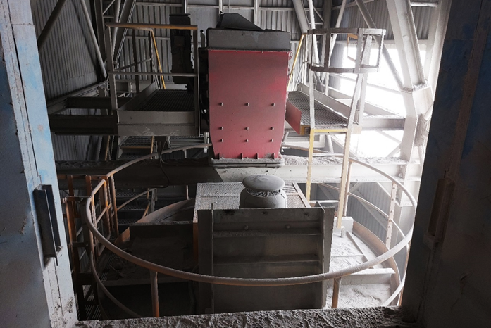
Fig. 1. Top view of the Anivi-Sturtevant classifier located on the processing line
2.1 Technical description
The Anivi-Sturtevant dynamic classifier consists mainly of the following elements, see figure 2:
- casing,
- inner cone,
- system of blades oriented according to the air flow,
- oversize cone,
- dynamic particle selection system,
- valve selection,
- drive unit.
The drive system consists of a vertical engine that transmits motion to the shaft of the dynamic system via trapezoidal belts. The drive engine is mounted on a bearing plate which is bolted to the support frame of the dynamic selection system located at the top of the device. The shaft drives the distribution plate, auxiliary blades, fan cone and main fan blades. The material feed duct is connected directly to the inner cone. The inner drum and cone closing the distribution plate and auxiliary blades form the selection chamber. The fixation of the inner drum and cone is carried out to the classifier casing by support arms. The selector valves are slid onto the top of the drum and cone and are mounted to the classifier casing by fixing supports. The air orientation blades are located under the cone of the lower drum. The oversize cone is located just below the orientation blades and is mounted to the classifier casing by support arms crossing the outlet duct.
The welded casing of the classifier is divided into two main parts: the upper cylinder, where material selection and separation is carried out, and the lower cone for collecting the product. The upper body is reinforced with robust brackets at four support points and it has an inspection door located on the top of the classifier. Some of internal main surfaces of the classifier that are in contact with the product and therefore liable to wear are protected by wear resistant lining [10].
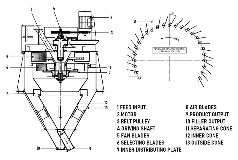
Fig. 2. Schematic view of the individual parts of the classifier (modified by [11])
2.2 Principle of the classifier
The shafts of the dynamic system, which rotate the various particle selection elements, are driven directly from the engine via belts and pulleys and in some cases via a gearbox. The material enters through an inlet duct and falls down onto the distributor plate to be pushed against the walls of the inner drum and cone by centrifugal forces. The coarser particles lose velocity on impact on the walls and fall by gravity onto the oversized cone where they are discharged through the outlet duct.
Smaller particles are pulled by the blades of the main fan which creates an air stream. As they move upwards, they meet the auxiliary blades (selection blades) which carry out major task in controlling the size of the product. A counter-fan blocks the path of uncoated particles and at the same time creates a centrifugal vortex. The blocking effect slows down the upward progress of larger particles, while allowing finer particles into the chamber. The centrifugal action throws the coarse particles against the walls of the lower drum and they then fall down into the oversized cone.
The fine particles that are not rejected are absorbed by the main fan which pushes them on the inner walls of the upper body of the classifier. They then fall gravitationally down onto the conical fine particle collector and are discharged through the outlet duct, see figure 3. The particulate-free air is again drawn in by the main fan and it is thus used in the next separation cycle [5, 10].
The theoretical expression of the flow in the classifier is very complex, but for a general idea it is based on the description of the forces acting on a spherical grain [5, 12, 13]. The grain is affected by the centrifugal force Fod, Archimedean buoyancy force FA and the environmental resistance force FR:
| (1) | ||
| (2) | ||
| (3) |
Where:
- ω … angular velocity of the particle [rad.s-1]
- r … radius of circularity (distance from the axis of the classifier) [m]
- vr … radial velocity of the particle [m.s-1]
- vt … circumferential (tangential) velocity of the particle [m.s-1]
Therefore, when the equilibrium state is reached, it must be valid:
|
|
|
(4) |
After fitting the values for the Rittinger and Stokes environmental resistance force, the final radial velocity of the particle for the Rittinger and Stokes flow regime can then be calculated:
|
|
|
(5) |
|
|
|
(6) |
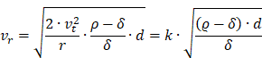
Thus, it can be concluded that analogous relations apply to the motion of the grain in the classifier as well as the motion in the static environment of the gravitational field. Only the relevant centrifugal acceleration is many times higher.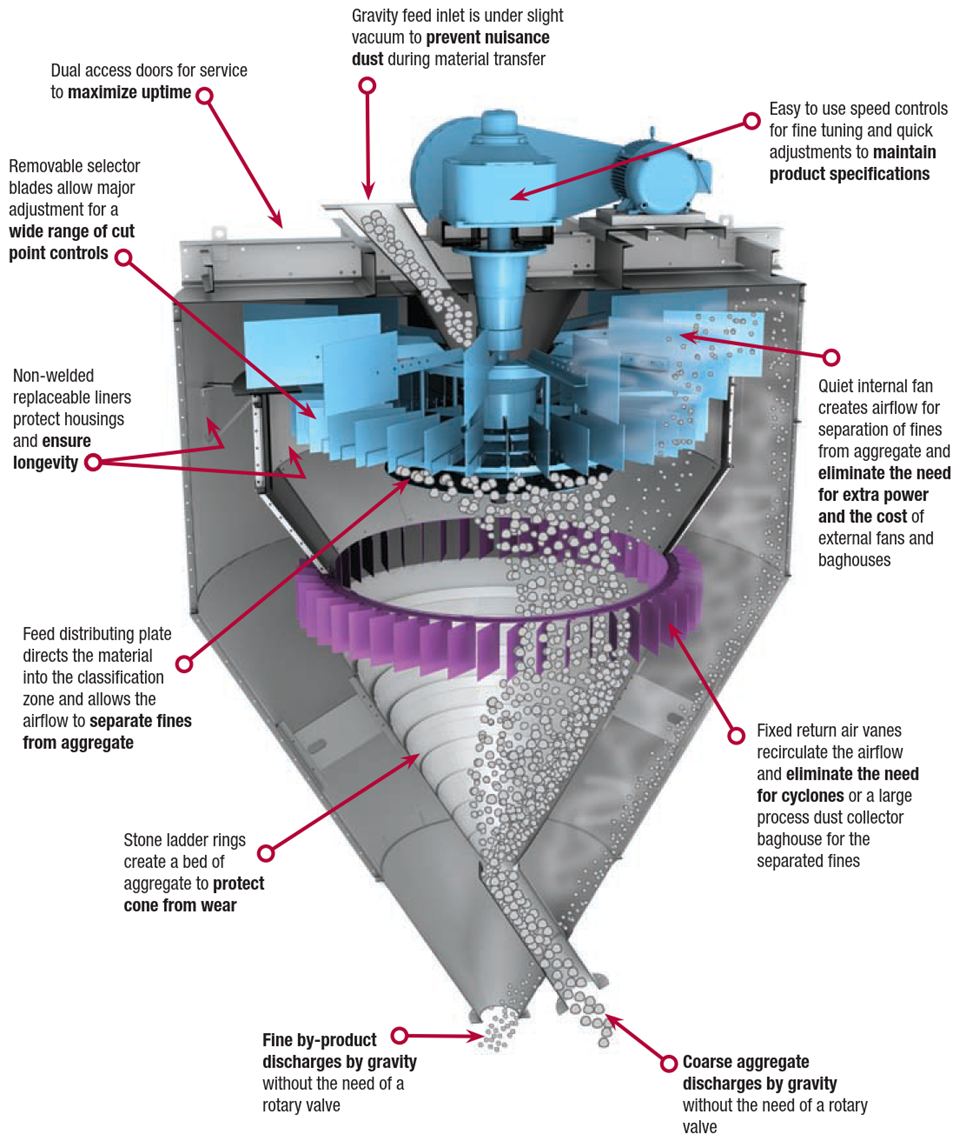
Fig. 3. Graphical representation of a particle flow classifier [14]
2. 3 Methodology
The methodology consisted of regular sampling of material at pre-selected sampling points. Samples were always taken according to a predetermined procedure and sampling was properly recorded in a sampling protocol.
2.3.1 Principle of sampling
Sampling was carried out by controlled sampling of the material from the conveyor belt using a special shovel. The shovel was inserted into the falling flow of material for a few seconds while the conveyor belt was running, thus filling the shovel from the full width of the belt, see figure 4. This procedure was subsequently repeated again. A total of two shovels were mixed together and then quartered into a quartering box. There are two containers in the quarter, one of which was emptied into a PVC bag (sample) and the other was emptied onto a conveyor belt (waste). This procedure was repeated until the PVC bag contained a sample of at least approximately 15 kg. The sample in the PVC bag was closed, labeled and transported to the laboratory as soon as possible. The sample was subjected to a granulometric test and a moisture test.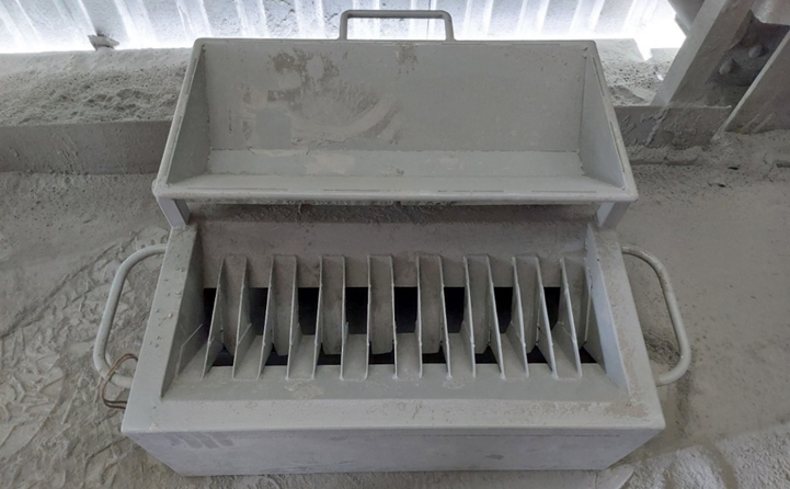
Fig. 4. Quartering box
Material samples were always taken from the input conveyor belt, see figure 5a, and the output conveyor belt, see figure 5b.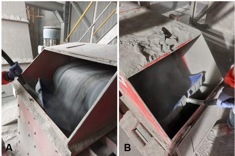
Fig. 5. Sampling with a special shovel: A) from input conveyor belt; B) from output conveyor belt
3 Results and discussion
As a part of the research on the Anivi-Sturtevant dynamic classifier, experiment in a quarry was carried out on a processing line in order to determine the efficiency of the equipment. In the experiment, samples were taken before entering and after leaving the equipment and subjected to granulometric test and moisture analysis.
3.1 Data processing
Data processing was performed in MS Excel where the data obtained by standardized analyses were sorted or modified. Microsoft Excel is a Microsoft spreadsheet that came on the market in 1993 and is currently part of the Microsoft 365 software package provided to customers as a rental service. It is therefore supported by the producer and therefore still up-to-date.
3.2 Results
As an input material, the combined material from the second and third crushing stages was used. The grain curve of the input material, see figure 6, shows some variation in the fine particle content (0.063 mm) ranging from 11.4 to 17.0 %. The fine particle content of the input material is directly influenced by the location of the last screen blast from which it is removed for the treatment process. If the material is more represented by the upper parts of the deposit, it contains more clay material and the material itself is more degraded by weathering.
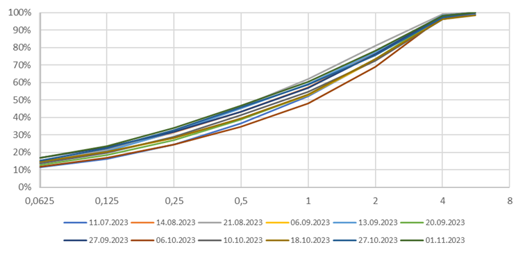
Fig. 6. Particle size distribution – feed
The grain size curve of the output material, see figure 7, shows the predicted reduction in the particle content which ranges from 2.9 to 8.7 %.
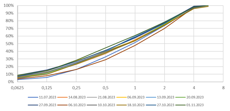
Fig. 7. Particle size distribution – product
Figure 8 shows the relation between the fine particle content and the moisture content of the final product. There is a clear trend. As the moisture content increases, the fine particle content of the product also increases.
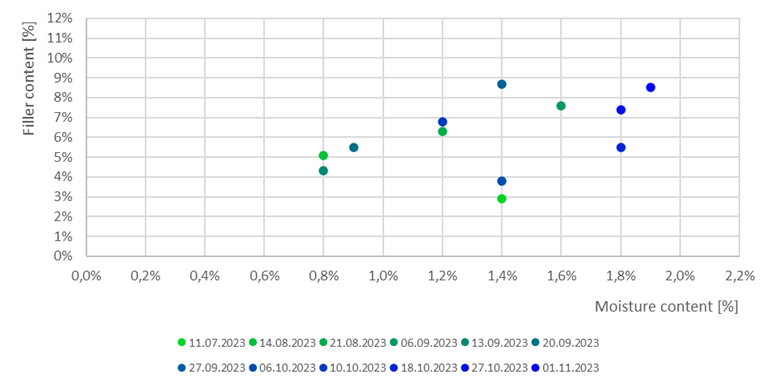
Fig. 8. Remaining filler in product
The efficiency of the ANIVI classifier is determined by the percentage of fine particles separated. In figure 9 can be observed that the separation efficiency is at a very good level ranging from 7 to 9,5 %. This efficiency was achieved independently of the moisture content of the input material.
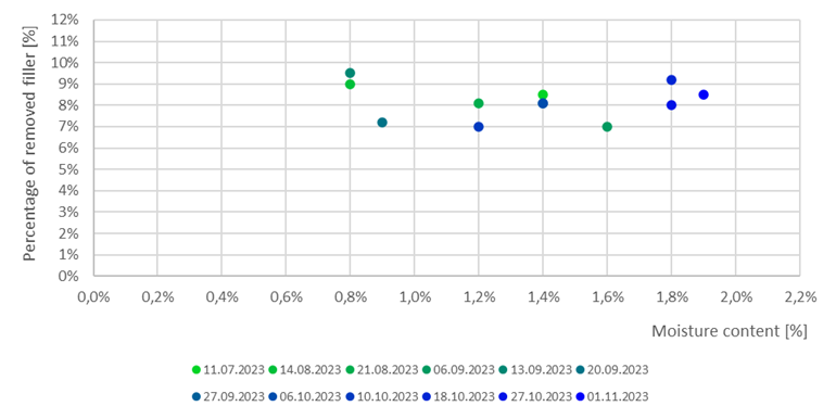
Fig. 9. Percentage of removed filler
3.3 Discussion
The Anivi-Sturtevant dynamic classifier is located on the crushed aggregate processing line to reduce the production of the 0/4 fraction of poor quality which is poor mainly due to the high proportion of fine particles. By separating the fine particles from the delivered 0/4 poor quality fraction, an uncategorized fraction (0/4 A) is produced by the classifier which does not meet the parameters for certification but is not so bad as to be defined as 0/4 fraction input. In order to eliminate the electricity consumption to produce it and to economically use the product 0/4 A, mixing models with fractions that are commonly sold were simulated. Thus, this is a deliberate reduction in product quality in order to make economic use of the classifier. As a condition for mixing 0/4 A into these fractions, the quality requirements of the fractions produced must be met.
Mixing 0/4 A with 0/4 certified (0/4 c) provides satisfactory results, see figure 10. By mixing these two components, the condition for a fine particle content of 10 % is met which is crucial for the customers of 0/4 certified. Oversized particles matter in excess of 1-4 mm is then considered a tolerable deficiency.
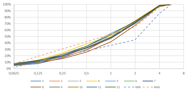
Fig. 10. Mixing model of the 0/4 A with 0/4 c in ratio 1:1
By mixing 0/4 A with 0/32 mixture, see figure 11, an increase of 0-4 mm particles is achieved which in the whole grain size range improves the product of the 0/32 fraction which has been deficient in these particles for a long time. By mixing these two fractions, the limit of a maximum fines content of 15 %, which is crucial for customers, is met.
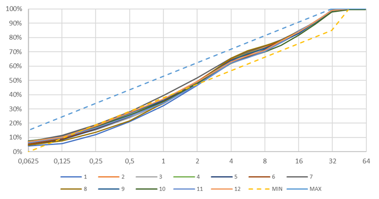
Fig. 11. Mixing model of the 0/4 A with 0/32 in ratio 1:1
By mixing 0/4 A with 0/63 mixture, see figure 12, an increase of 0-4 mm particles is achieved which in the whole grain size range, as in the previous case, improves the product of the 0/63 fraction, which is deficient in these particles in the long term. By mixing these two fractions, the limit of a maximum fines content of 15 %, which is crucial for customers, is met.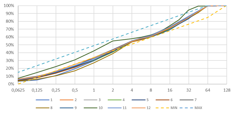
Fig. 12. Mixing model of the 0/4 A with 0/63 in ratio 1:1
In general, the possibility of mixing a 0/4 A product is realistic and it is recommended. If the product is to be dumped and not used for this purpose, the better option is not to operate the equipment at all due to the electricity consumption.
4 Conclusions
In 2023, the applicability of the Anivi-Sturtevant dynamic classifier, which is located on the processing line at the crushed aggregate quarry, was analyzed. The aim of the analysis was to verify the economic viability of its use, mainly in terms of efficiency of the equipment and the recovery of the uncategorized fraction produced.
The efficiency of the Anivi-Sturtevant classifier is influenced by the quality of the input material, i.e. the fine particle content, its moisture content and the quantity supplied for separation. If the input material is taken from the first stages, which are rich in clay particles and are moderately to heavily weathered, they will contain a higher fine particle content and the material is likely to be wetter than good quality material. Input material with a moisture content higher than 2 % subsequently affects the operation of the classifier due to the higher adhesion of the material which may result in sealing of the classifier blades. The classifier has a guaranteed production capacity of 40 t∙hod-1. However, the use of this maximum capacity reduces the efficiency of the equipment. It has been found that the highest efficiency has equipment up to 30 t∙hod-1.
In the experiment, the operating efficiency of the device was found to be in the range of 7.0 to 9,5 % of fines separated. Thus, the average efficiency of the equipment is 8.25 %. Furthermore, the recoverability of the produced material by mixing with commonly produced fractions was verified. The produced fraction 0/4 A can be mixed in a ratio 1:1 into 0/4 certified and into 0/32 and 0/63 mixtures.
Acknowledgements
This research was supported by the VSB – Technical University of Ostrava under Project SP2024/029 "Implementation of integrated unmanned aerial systems and virtual technologies for precise mapping and complex monitoring of environmental hazards".
References
- Darmann, S. (2014). Optimization of an Air Classifier. Diploma Thesis. Graz: Technical University, 86 p.
- Shapiro, M. & Galperin, V. (2005). Air Classification of Solid Particles: A Review. Chemical Engineering and Processing, vol. 44: 279-285. DOI: 10.1016/j.cep.2004.02.022
- Furchner, B. & Zampini, S. (2009). Air Classifying. Ullmann’s Encyclopedia of Industrial Chemistry, vol. 2: 215-234. DOI: 10.1002/14356007.b02_17.pub2
- Leschonsi, K. & Legenhausen, K. (1992). Investigation of the Flow Field in Deflector Wheel Classifiers. Chemical Engineering and Processing: Process Intensification, vol. 31(2): 131-136. DOI: 10.1016/0255-2701(92)85007-O
- Klumpar, I., V., Currier, F., N., Ring, T., A. (1986). Air Classifiers. Chemical Engineering, vol. 3: 77-92.
- Kukuricasova, J. (2017). Application of Technology to Reduce Fine Particles in the Final Product in a Quarry Bystřec. Bachelor Thesis. Ostrava: VŠB-Technical University of Ostrava, 59 p. (in Czech)
- Anivi Ingenieria. (2010). Dry Process – Grinding and Micronizing. Technical Report. Bilbao: Anivi Ingenieria, S. A., 12 p.
- Anivi Ingenieria. (2006). High Fineness Classification. Technical Report. Bilbao: Anivi Ingenieria, S. A., 8 p.
- Klumpar, I., V., Zoubov, N., N. (1985). New Sturtevant High Efficiency SD Classifier at Keystone Cement. World Cem., vol. 10: 23-29.
- Anivi Ingenieria (2016). Machine: „ANIVI-STURTEVANT“ Dynamic Classifier. Technical Report. Bilbao: Anivi Ingenieria, S. A., 10 p.
- Anivi Ingenieria. (2016). Classifier type A.S. – Spare Parts. Technical Report. Bilbao: Anivi Ingenieria, S. A., 1 p.
- Botula, J., Vidlar, J. (2018). Mineral Waste Treatment II – Branching Processes. Ostrava: VŠB-Technical University of Ostrava, 132 p. (in Czech)
- Barimani, M., Green, S., Rogak, S. (2018). Particulate Concentration Distribution in Centrifugal Air Classifiers. Mineral Engineering, vol. 126: 44-51. DOI: 10.1016/j.mineng.2018.06.007
- Sturtevant (2015). Sturtevant – Solutions for Stone, Sand and Gravel. Technical Report. Hanover: Sturtevant, Inc., 12 p.
Conflict of Interest Statement
The authors declare that there is no conflict of interest regarding the publication of this paper.
Author Contributions
Data Availability Statement
There is no dataset associated with the study or data is not shared.
Supplementary Materials
There are no supplementary materials to include.