Volume 24 article 1333 pages: 299-312
Received: Nov 28, 2025 Accepted: Mar 19, 2026 Available Online: Apr 12, 2026 Published: Apr 30, 2026
DOI: 10.5937/jaes0-63089
ELASTOHYDRODYNAMIC ANALYSIS OF MULTISTEP TEXTURED JOURNAL BEARINGS WITH GROOVE DEPTH VARIATIONS USING CFD–FSI
Abstract
Journal bearings are widely employed in numerous industrial machines such as compressors, pumps, turbines, and generators, primarily to support rotating shafts. Compared with other surface texturing geometries, multistep journal bearing represents a geometric modification of conventional designs and is increasingly adopted because of its simple configuration, low manufacturing cost, and ease of fabrication. The stepped profile also facilitates greater lubricant flow, thereby enhancing the bearing’s operational performance. Extensive research has been devoted to evaluating parameters such as pressure distribution, load-carrying capacity, frictional forces and elastic deformation to improve tribological characteristics of journal bearings. This work investigates the influence of groove geometry—specifically groove height and width on the performance of multistep journal bearings in order to develop an optimized configuration. Three-dimensional computational fluid dynamics (CFD) simulations coupled with fluid-structure interaction (FSI) analysis, including cavitation effects, were performed. The results reveal that increasing the number of steps reduces frictional forces, while the load-carrying capacity decreases slightly. For instance, at a groove width of 35°, the load-carrying capacity was 6.96 % lower than at 15°, yet the frictional performance improved by 14.5 %.
Highlights
- Tribological behaviour of multistep textured journal bearings operating with varying eccentricity ratios
- Elastohydrodynamic analysis of the influence of multistep texture with variations in groove depth on journal bearing performance
- Computational Fluid Dynamics (CFD) and Fluid Structure Interaction methods are used in multi-step journal bearing simulations.
Keywords
Content
1 Introduction
Bearings serve a fundamental function in machinery by reducing friction between moving parts. Among the various types, anti-friction (rolling element) bearings and hydrodynamic journal bearings are the most prevalent in industrial applications. The primary role of a bearing is to transmit load from the rotor to the housing with minimal wear and energy loss [1].
Because of their simple structure and effective damping properties, journal bearings are frequently selected for mechanical systems operating at both low and high rotational speeds. Ensuring adequate lubrication performance is essential to meet stability and safety requirements [2]. Considerable attention has been given to parameters such as pressure distribution, load-carrying capacity, frictional forces, cavitation behaviour, and elastic deformation to enhance the tribological efficiency of journal bearings. In particular, the combined effects of cavitation and fluid–structure interaction (FSI) under elastohydrodynamic lubrication (EHL) conditions remain a critical area of investigation. Charamis et al. report that cavitation-manifested by vapor bubble formation within the lubricant-markedly alters pressure profiles and diminishes lubrication effectiveness, thereby underscoring the importance of accurate prediction and simulation. CFD-based modelling has thus become indispensable for capturing cavitation phenomena and for optimizing bearing geometries to improve lubrication performance [3].
Modern industrial trends toward heavy rotor loads and high rotational speeds [4] have further highlighted the need to understand dynamic behaviour and clearance faults in journal bearings. Research on reciprocating compressors, for example, has demonstrated that weak signal detection of clearance faults under noisy conditions is essential for performance monitoring and aligns with deformation analyses in multistep journal bearings [5].
Surface texturing of bearings-an approach rooted in nanomechanics and biomimetics—has been widely explored as a means of performance enhancement [6]. A systematic review of surface texturing for tribological applications has demonstrated that texture shape, aspect ratio, texture density, orientation, and lubrication regime collectively govern friction reduction and load-carrying enhancement [7]. Compared with other textures, the multistep concept is relatively simple. Unlike micro-textures that require numerous fine indentations, multisteps use fewer but larger features, thereby improving lubricant retention. Increasing the number of steps has been shown to decrease cavitation zones. Bompos and Nikolakopoulos [8] reported improvements in load capacity and friction coefficient for certain configurations. Chen et al. [9] similarly demonstrated that groove geometry significantly influences journal bearing behaviour. Numerous studies have confirmed that surface textures, including multistep patterns and partial surface roughness, exert a pronounced effect on the tribological response of bearings [10]. The location of steps also matters: if the step is placed closer to the attitude angle, friction increases and performance declines. Variations in geometric stage number affect frictional force, temperature, and vapor fraction, and excessive steps can impair performance. Therefore, the appropriate texture size should be carefully optimized to enhance the tribological performance of journal bearings [11].
Journal bearings also operate under conditions of misalignment and extreme loads. Work by Wu et al. and Tauviqirrahman et al. has shown that combined misalignment, load, and speed variations can substantially degrade performance [12]. Bompos and Nikolakopoulos concluded that for three-step pressure distributions, steps should be separated rather than adjacent. Minimum fluid film thickness should be near, but not inside, the step region, and eccentricity should exceed 0.75 to sustain load. Optimal parameters include an L/D ratio of 5, eccentricity of 0.9, step orientation of 5°, step depth six times the clearance, and attitude angle of 64.7°.
Water-lubricated bearings (WLBs) offer environmentally friendly alternatives but suffer from increased wear and friction due to the low viscosity of water. Consequently, improved textures are required to enhance their performance [13]. Although journal bearings are often assumed to operate under isothermal and laminar conditions, in reality they may experience turbulence and heat generation due to fluid friction. Li et al. explored the potential of water lubrication for reducing environmental impact and improving performance in marine and offshore systems, but emphasized that low viscosity imposes significant challenges, necessitating new surface textures and lubrication strategies [14].
Benasciutti et al. [15] performed a static analysis of elastohydrodynamic journal bearings and found that elastic deformation yielded a more uniform pressure distribution compared with rigid cases. Such deformation directly affects load-carrying capacity and frictional force [16]. The maximum pressure peaks were reduced while the maximum radial stress modulus exceeded the von Mises stress. Modelling EHL typically begins with a simplified Reynolds equation derived from momentum and continuity equations under incompressible isoviscous assumptions, but modern approaches incorporate compressibility, piezoviscosity, and non-Newtonian effects [17]. Advanced diagnostic techniques such as PSO-optimized SVM have also been developed to detect bearing faults under varying speeds, reinforcing the importance of high-speed conditions in stability assessments [18].
Lubrication remains a cornerstone of mechanical system reliability. By maintaining a thin film between contacting surfaces, lubricants prevent metal-to-metal contact and reduce the risk of failure. Accurate prediction of film thickness is therefore vital for robust design. In many tribological interfaces, the pressures are sufficient to induce significant elastic deformation of contacting bodies, which in turn facilitates the formation of a stable film—an effect known as elastohydrodynamic lubrication (EHD). Because EHD couples elasticity, hydrodynamics, and lubricant rheology, the problem is highly nonlinear and complex to solve [19]. Notwithstanding the advancements in elastohydrodynamic modelling, several fundamental aspects of tribological contact extend beyond conventional fluid–structure interaction analyses. The contact behaviour of rough surfaces governs the real contact area and load-sharing mechanisms, as described by statistical asperity-based models such as the Greenwood–Tripp formulation [20]. Moreover, frictional processes are intrinsically irreversible and involve continuous energy dissipation and entropy generation, thereby requiring thermodynamic consideration of mass, energy, and entropy balances in open tribo-systems [21]. In addition, tribological interfaces may exhibit self-organizing mechanisms that promote adaptive surface evolution and friction stabilization [22]. The present work, however, concentrates specifically on the elastohydrodynamic response of multistep textured journal bearings with groove depth variations, investigated through coupled CFD–FSI simulations.
2 Materials and methods
2.1 Method
The multistep configuration adopted in this study was derived from the design principles proposed by Bompos and Nikolakopoulos [8]. The number and height of the grooves were determined according to the reference parameters outlined in their work. Validation of the present model was performed by comparing simulation outcomes with those reported by Dhande and Pande [23].
The simulations were performed using the ANSYS CFD and fluid–structure interaction (FSI) modules to model journal bearing performance under lubricated conditions, explicitly incorporating cavitation effects. These simulations enabled comparison of maximum hydrodynamic pressure and bearing deformation to ensure model reliability. The journal and bearing were modelled as structural steel, whereas the lubricant was defined as fuel oil, consistent with the material properties adopted in the referenced validation study [23].
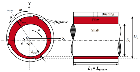
Fig. 1. Multistep journal bearing geometry schematic
Figure 1 schematically illustrates the geometry of the multistep journal bearing, consisting of a shaft, bushing, and a lubricant film. The parameter e represents the radial displacement of the journal center with respect to the bearing center, which directly influences the lubricant film thickness distribution, and are expressed in an X–Y coordinate system along with the attitude angle φ. Parameters hmin, hmax, and Dj represent the minimum film thickness, maximum film thickness, and journal diameter, respectively, while Lb denotes the bearing length. The bearing diameters (Db and Dj) and the corresponding radial clearance, defined as (Db − Dj)/2, represent nominal values used in the numerical model.Parameters Rer and Rec represent the rotational Reynolds number and the critical Reynolds number, respectively, where Rer characterizes the lubricant flow regime and Rec indicates the onset of turbulence.
Table 1. Parameters of multistep journal bearing high groove geometry modeling
|
Parameters |
Symbol |
Value |
Unit |
|
Journal diameter |
Dj |
50 |
mm |
|
Bushing diameter |
Db |
50.1 |
mm |
|
Bushing length |
Lb |
25 |
mm |
|
Radial clearance |
c |
0.05 |
mm |
|
Eccentricity Ratio |
ε
|
0.8 |
- |
|
Attitude Angle |
φ |
35° |
- |
|
Shaft rotating speed |
n |
4,000 |
rpm |
|
Arc length steps |
g |
30 |
° |
|
Arc length between steps |
b |
90 |
° |
|
Groove length |
Lgroove |
25 |
mm |
|
Groove height |
Hgroove |
0.1; 0.2; 0.3; 0.4 |
mm |
Table 2. Flow conditions at eccentricity ε = 0,8 and n = 4.000 rpm
|
Geometry |
Speed Rotation |
Rer |
Rec |
Flow |
|
Smooth |
4,000 rpm |
355.8 |
0.0889 |
Turbulent |
|
Multistep Hgroove = 0.1 mm |
4,000 rpm |
1,067.6 |
0.2669 |
Turbulent |
|
Multistep Hgroove = 0.2 mm |
4,000 rpm |
1,779.3 |
0.4448 |
Turbulent |
|
Multistep Hgroove = 0.3 mm |
4,000 rpm |
2,491.1 |
0.6227 |
Turbulent |
|
Multistep Hgroove = 0.4 mm |
4,000 rpm |
3,202.8 |
0.8007 |
Turbulent |
Table 3. Parameters of multistep journal bearing groove width geometry modeling
|
Parameters |
Symbol |
Value |
Unit |
|
Shaft rotating speed |
n |
4,000 |
rpm |
|
Arc length steps |
g |
15, 20, 25, 30, 35 |
° |
|
Groove length |
Lgroove |
25 |
mm |
|
Groove height |
Hgroove |
0.3 |
mm |
Tables 1–3 summarize the main modelling parameters. Table 1 provides the baseline bearing geometry; Table 2 details the corresponding flow conditions that confirm a turbulent regime; and Table 3 lists groove-width variations for assessing their effect on pressure and load capacity. Collectively, these tables establish the numerical framework that links geometry, flow characteristics, and groove design.
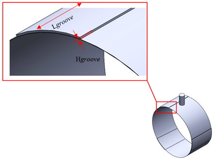
Fig. 2. 3D model multistep groove journal bearing
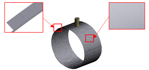
Fig. 3. Meshing fluid domain in multistep groove journal bearing
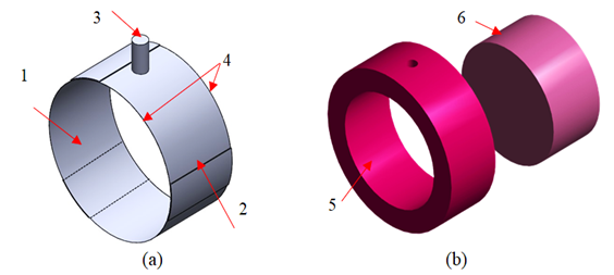
Fig. 4. Boundary conditions in the validation case: (a) Fluid domain (b) Solid domain; (1) Moving wall, (2) Stationary wall, (3) Inlet, and (4) Outlet (5) Contact pressure stationary wall (6) Contact pressure moving wall
Figures 2–4 depict the modelling workflow. Figure 2 shows the three-dimensional model of the multistep groove bearing; Figure 3 presents the meshing of solid and fluid domains used to capture flow and pressure fields. The fluid domain was meshed using a multizone sweep method with six divisions across the film thickness and a characteristic element size of 4 × 10⁻⁴ m, resulting in 153,302 elements and 181,728 nodes. The solid domain was discretized with a body sizing of 14 × 10⁻⁴ m, generating 187,030 elements and 67,277 nodes, ensuring adequate mesh quality for both CFD and structural analyses; and Figure 4 defines the boundary conditions, including inlet, outlet, stationary walls, and moving walls. The fluid–solid interface and cylindrical support were specified in accordance with these boundary conditions to ensure proper transfer of fluid pressure loads to the structural domain.
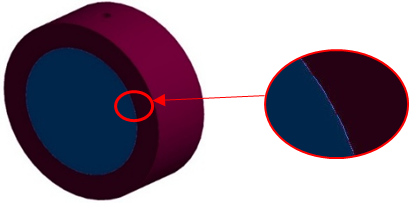
Fig. 5. Definition of fluid-solid interface
Figure 5 highlights this fluid–solid interface, which serves as the coupling region transferring pressure distributions from the fluid domain to the structural domain. Accurate definition of this interface is critical for reliable FSI analysis, as it governs the interaction between fluid dynamics and structural response, thereby enabling credible predictions of deformation and stress fields under realistic operating conditions. The numerical simulations were performed using a pressure-based steady-state solver. Pressure–velocity coupling was handled using the SIMPLE scheme. Spatial discretization employed the Least Squares Cell-Based method for gradient evaluation, PRESTO! for pressure interpolation, Second-Order Upwind for momentum equations, and QUICK for volume fraction. Convergence was monitored based on residual criteria to ensure solution stability.
2.2 Governing equation
The simulations are governed by the Navier–Stokes equations and the principle of mass conservation [2]. The mass conservation equation for unsteady flow can be expressed as:
where is the operator vector, is the density of the lubricating fluid, is the velocity vector of the lubricating fluid, and t is the time used to calculate the lubrication fluid under unsteady flow conditions.
Momentum conservation is expressed as:
where P is the static pressure, and is the gravitational force and the external force, respectively. While is the voltage tensor.
Journal bearing performance was assessed based on three primary parameters: load-carrying capacity and frictional force. The load-carrying capacity corresponds to the integrated pressure distribution over the bearing surface and the total supported load. Mathematically, it can be expressed as [24]:
where A is the total bearing area and p is the amount of hydrodynamic pressure created along the journal bearing's surface.
The integral of the shear stress along the journal bearing's surface is used to determine frictional force. Mathematically the frictional force that occurs in the journal bearing can be expressed as equation 4 below [24].
where A is the entire bearing area and τ represents the shear stress generated in the journal in the rotational direction.
2.3 Validation
To ensure the validity of the research methodology, the present results were compared with baseline data reported by Dhande and Pande [23]. Specifically, maximum hydrodynamic pressure and bearing deformation values were contrasted. Difference in Pmax value at a shaft speed is 1,000 rpm, the difference in results is 0.67% and the difference in the value of deformation in the bearing Sbmax by 4.84 %, the details of validation can be seen in Figure 6.
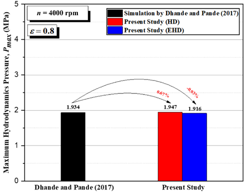
Fig. 6. Comparison of journal bearing maximum pressure value at e = 0.8 between Dhande and Pande [18] with present study on shaft speed of 1,000 rpm
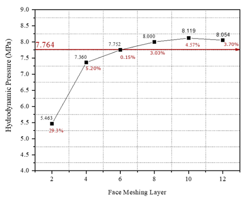
Fig. 7. Grid independence test of journal bearing at = 0.8, with shaft speed 1000 rpm
Figures 6 and 7 provide validation results. Figure 6 shows a bar chart comparing maximum pressure values between the present study and Dhande & Pande at an eccentricity ratio of ε = 0.8 and shaft speed of 1000 rpm. Figure 7 presents the grid-independence study, indicating how maximum hydrodynamic pressure converges with increasing mesh density. The value of 7.764 MPa corresponds to the validated maximum pressure reported in the referenced journal study. Six mesh layers were ultimately selected to balance computational cost and accuracy, and this configuration was applied in all subsequent simulations to ensure consistent, reliable evaluation.
3 Results and discussion
3.1 Effect of multistep journal bearing high geometry modeling
3.1.1 Simulation results of multistep groove height variation on journal bearing performance with turbulent flow modeling
3.1.1.1 Pressure
The pressure profiles for multistep‐grooved and smooth journal bearings exhibit comparable overall shapes. However, the grooved configuration produces slightly different peak pressures. This indicates that introducing multistep grooves modifies the hydrodynamic pressure field within the lubricant, albeit with only a modest effect on lubrication efficiency under the examined conditions [25].
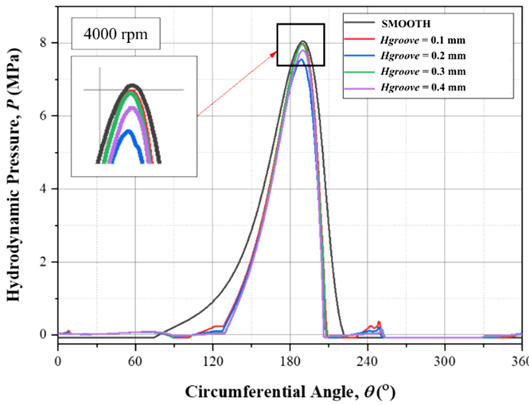
Fig. 8. Pressure distribution on multistep groove and smooth journal bearing with ε = 0.8
Figure 8 illustrates the hydrodynamic pressure distribution of multistep and smooth bearings at an eccentricity ratio of ε = 0.8 and a rotational speed of 4,000 rpm. In both cases, the highest pressure occurs at similar circumferential positions. Nevertheless, the multistep geometry generates noticeably elevated local pressures, which suggests an enhancement in load-supporting capability compared with the smooth surface. These observations confirm that groove geometry directly influences pressure generation in the lubricating film.
3.1.1.2 Deformation
Bearing and shaft deformation values produced by multistep groove journal bearings are lower than smooth journal bearings with elastohydrodynamics lubrication at an eccentricity ratio ε = 0.8 and rotational speed n = 4,000 rpm. This highlights how the journal bearing's multistep groove can slightly improve lubrication performance by minimizing distortion.
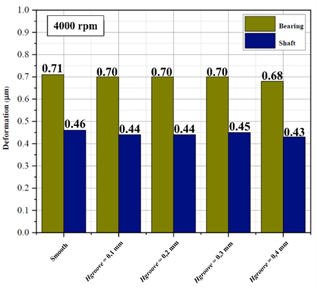
Fig. 9. Deformation in bearings and shafts with ε = 0.8
Figure 9 presents the deformation data, illustrating how grooved bearings sustain less distortion compared with smooth designs. This result highlights the grooves’ ability to distribute loads more evenly and reduce structural stress during operation. The deformation of the bearing and shaft under elastohydrodynamic conditions is lower in multistep configurations than in smooth ones. This reduction implies that multistep grooves promote a more uniform pressure field and hence improve lubrication efficiency and mechanical stability at ε = 0.8 and n = 4,000 rpm.
3.1.1.3 Load carrying capacity
Introducing multistep grooves slightly decreases the bearing’s load-carrying capacity (LCC) relative to a smooth surface under the same operating conditions. Load-carrying capacity is determined by integrating the hydrodynamic pressure distribution over the bearing surface area, representing the resultant normal force supported by the lubricant film [26].
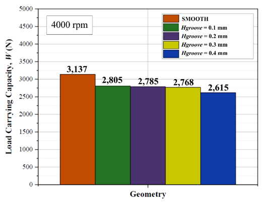
Fig. 10. Load carrying capacity multistep groove and smooth journal bearing with ε = 0.8
Figure 10 illustrates load-carrying capacity between smooth journal bearings and grooved journal bearings. The figure presents load capacity data for smooth bearing and several grooved bearings with varying groove depths. All measurements were conducted under identical operating conditions, namely at an eccentricity ratio (𝜀 = 0.8) and a rotational speed (n = 4,000 rpm).
3.1.1.4 Friction force
Reducing frictional losses is crucial for improving journal bearing efficiency [7]. The friction force in a journal bearing is obtained by integrating the hydrodynamic shear stress distribution along the bearing surface, representing the resultant tangential force transmitted by the lubricant film [27]. Across all groove heights studied, multistep grooved bearings demonstrated lower frictional forces than the smooth bearing—by approximately 13.9 % at 0.1 mm groove height, 14.6 % at 0.2 mm, 15.7 % at 0.3 mm, and 16.6 % at 0.4 mm. Figure 11 plots these results, showing a consistent friction reduction for grooved designs compared with the smooth surface. This decrease directly translates into enhanced performance and energy efficiency.
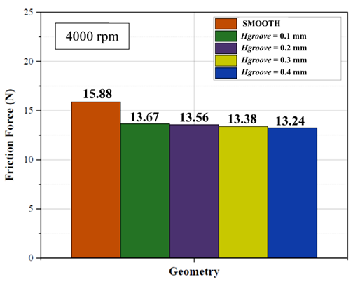
Fig. 11. Friction force on multistep groove and smooth journal bearing with ε = 0.8
Simulations were conducted at a rotational speed of 4,000 rpm and an eccentricity ratio (𝜀 = 0.8). The results indicate a significant reduction in friction for grooved bearings compared to the smooth bearing. This reduction is particularly important, as it directly relates to the overall enhancement of bearing performance and efficiency.
3.1.1.5 Coefficient of friction
The coefficient of friction (COF) is a fundamental parameter used to evaluate the tribological performance of journal bearings. It represents the ratio between the friction force generated at the lubricated interface and the applied normal load [28]. Figure 12 illustrates the obtained COF values, indicating that grooved configurations generally exhibit lower friction compared to the smooth surface. The reduction is most noticeable at moderate groove depths, while an excessive depth slightly increases friction.
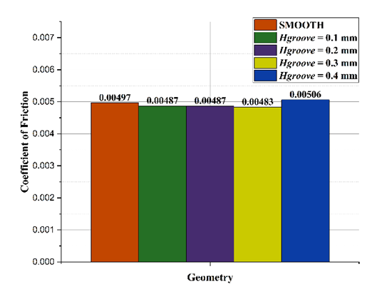
Fig. 12. Coefficient of friction on multistep groove and smooth journal bearing with ε = 0.8 and n = 4000 rpm
As shown in Figure 12, the smooth surface produces a COF of 0.00497. Introducing groove depths of 0.1 mm and 0.2 mm reduces the COF to 0.00487, while a depth of 0.3 mm results in the lowest value of 0.00483. According to the literature, lubrication regimes bordering mixed lubrication are classified as 0.002–0.05 for elastohydrodynamic lubrication (EHL) and 0.05–0.15 for boundary lubrication. Since all obtained COF values fall within the range of 0.002–0.05, the bearing operates under an elastohydrodynamic lubrication regime rather than boundary lubrication [29].
3.2 Effect of multistep journal bearing wide geometry modeling
This section evaluates how variations in groove width influence the performance of multistep journal bearings. Simulations were carried out at a groove height of 0.3 mm, adjusting the angular width of each step to assess changes in pressure distribution, deformation, load-carrying capacity, and frictional force.
3.2.1 Simulation results of multistep groove width on journal bearing performance with turbulent flow modeling
3.2.1.1 Pressure
The multistep groove journal bearing produces less maximum pressure than the smooth journal bearing. This demonstrates how a multistep groove on the journal bearing has a minor impact on lubrication performance when pressure is reduced [19].
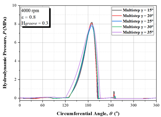
Fig. 13. Pressure distribution on multistep groove journal bearing with variation groove widths
Hydrodynamic pressure profiles for multistep bearings with different groove widths show similar general shapes but exhibit subtle differences in peak values. Figure 13 presents the pressure distribution for bearings operating at ε= 0.8 and n = 4,000 rpm with a groove height of 0.3 mm. The three curves, corresponding to groove angles of 25°, 26°, and 27°, demonstrate that step width slightly alters the pressure pattern. This indicates that groove geometry can be tuned to optimize load support and efficiency.
3.2.1.2 Deformation
Deformation discrepancies from smooth journal bearings with ε = 0.8 and rotational speed n = 4,000 rpm generated from the bearing and shaft deformation values produced by multistep groove journal bearings with multistep width variations. This highlights how a difference in the maximum deformation value might slightly influence the lubrication performance when a multistep groove is added to the journal bearing [2].
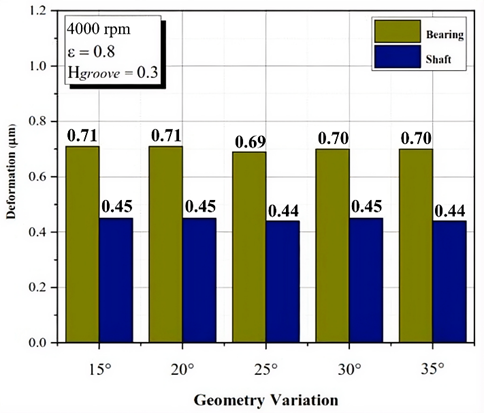
Fig. 14. Deformation in bearings and shafts with variation groove widths
Figure 14 compares the maximum deformation of bearings and shafts for various groove geometries. Under identical operating conditions, grooved bearings generally display reduced deformation compared with smooth designs, as evidenced by the deformation results presented in Figure 9. Increasing groove height slightly decreases bearing deformation, whereas shaft deformation remains relatively stable. This indicates that groove geometry enhances load distribution and structural stability, thereby improving reliability at high speeds.
3.2.1.3 Load carrying capacity
The load carrying capacity (LCC) of the multistep groove journal bearing is inversely related to the eccentricity ratio ε = 0.8, rotating speed n = 4,000 rpm, and Hgroove 0.3 mm. The narrower the multistep journal bearing's width, the higher the load carrying capacity value. This shows that the addition of a multistep groove on the journal bearing reduces the load carrying capacity (LCC) [2].
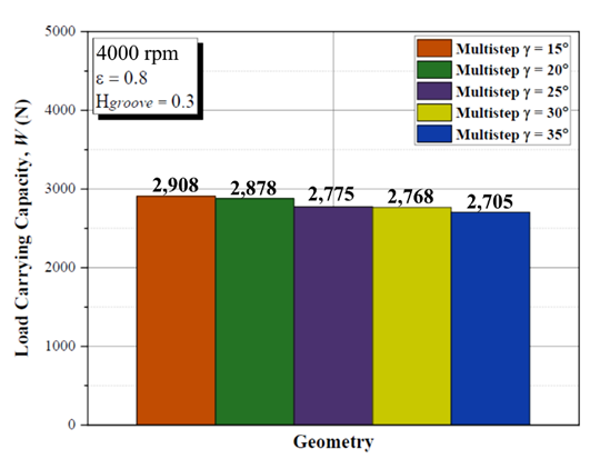
Fig. 15. Load carrying capacity multistep groove journal bearing with variation groove widths
Figure 15 shows a comparison of load-carrying capacity in journal bearings. The graph displays load capacity data for grooved bearings with five groove width variations (15°, 20°, 25°, 30°, and 35°). Measurements were conducted at an eccentricity ratio (𝜀 = 0.8), a rotational speed of 4,000 rpm, and a groove height of 0.3 mm. The results illustrate the relationship between groove width and bearing performance in supporting load.
3.2.1.4 Friction force
The multistep journal bearing with the maximum multistep width value has a lower friction force value, as can be seen from the graph of friction force in Figure 16. This indicates that the friction force decreases as the width of the multistep groove on the journal bearing increases.
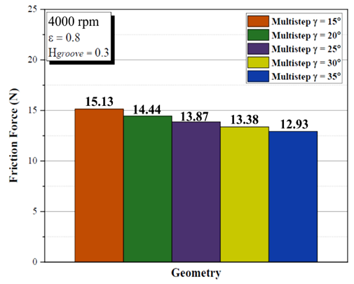
Fig. 16. Friction force on multistep groove journal bearing with variation groove widths
The data show that larger step widths tend to reduce friction more effectively, thereby improving lubrication efficiency and mechanical behavior. These findings reinforce the importance of optimizing groove geometry to minimize energy losses and enhance overall bearing performance.
3.2.1.5. Coefficient of friction
Figure 17 presents the calculated coefficient of friction (COF) for various multistep angles (γ), highlighting the influence of geometric variation on frictional behavior. The results demonstrate a progressive decrease in COF with increasing angle, indicating that larger multistep angles contribute to improved lubrication performance.
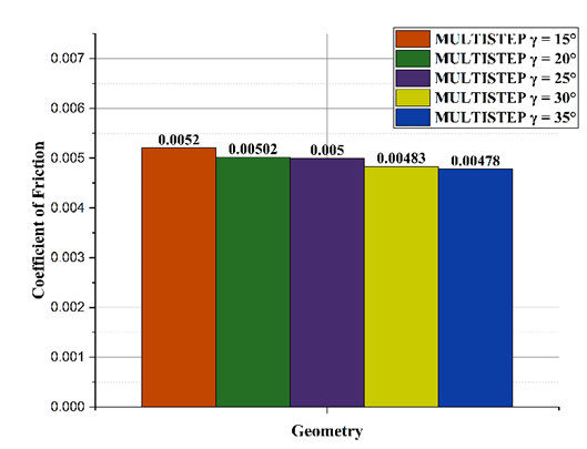
Fig. 17. Coefficient of friction on multistep groove journal bearing with variation groove widths
The calculated coefficient of friction ranges between 0.00478 and 0.0052. The measurements were conducted at an eccentricity ratio (ε = 0.8), a rotational speed of 4,000 rpm, and a groove height of 0.3 mm. According to the literature, lubrication regimes bordering mixed lubrication are classified as follows: 0.002–0.05 for elastohydrodynamic lubrication (EHL) and 0.05–0.15 for boundary lubrication. Since the obtained COF values fall within the range of 0.002–0.05, the lubrication regime in the present study can be categorized as elastohydrodynamic lubrication rather than boundary lubrication [29].
4 Conclusions
This study investigated the tribological behaviour of multistep-textured journal bearings under operating conditions of an eccentricity ratio of ε = 0.8 and a rotational speed of n = 4,000 rpm, with particular attention to the influence of geometric parameters such as step height and step width on bearing performance. The effects of these parameters on load-carrying capacity and frictional force were analysed. The following conclusions summarise the results of the present study:
- The geometric configuration of multistep textures significantly affects the tribological performance of journal bearings. Variations in step height influence the load-carrying capacity and frictional force. Increasing the step height tends to reduce both the load-carrying capacity and frictional force.
- The optimum performance with respect to load-carrying capacity and frictional characteristics is obtained at a groove height of 0.3 mm, indicating that moderate step depths provide a balanced hydrodynamic pressure generation within the lubricant film.
- Step width also plays an important role in determining bearing performance under the same operating conditions. Increasing the step width results in a decrease in both the average load-carrying capacity and frictional force, with the best overall performance achieved at a step width of 35°.
For future research, the validation of the experiment will be our priority with respect to the bearing performance, for example measuring the friction force and the load carrying capacity. Besides, other parameters like temperature, type of lubricants will be our next topics of research in the future.
Acknowledgements
This research was funded by Direktorat Riset, Teknologi, dan Pengabdian Masyarakat—Kementerian Riset dan Teknologi Republik Indonesia (DRPM-Kemenristek) through the Fundamental Grant number 359–053/UN7.D2.1/PP/VII/2025 and the Institute Research and Community Services LPPM Diponegoro University in Indonesia for their financial support through grant of RPI, under grant number 222-560/UN7.D2/PP/IV/2025.
References
- Malcom, E., Leader, P. (2001). Understanding journal bearings. Appl Mach Dyn Co.
- Chen, Y., Sun, Y., He, Q., Feng, J. (2019). Elastohydrodynamic behavior analysis of journal bearing using fluid–structure interaction considering cavitation. Arabian Journal for Science and Engineering, 44(2), 1305–1320. https://doi.org/10.1007/s13369-018-3467-9
- Hameed, M. R., Ali, S. A., Hadwan, H. H., Toman, A. A., Mahdi, M. A. (2024). CFD-FSI analysis of textured journal bearing working with nano lubricant. Diagnostica, 25(2). https://doi.org/10.29354/diag/188391
- Sahu, M., Giri, A. K., Das, A. (2012). Thermohydrodynamic analysis of a journal bearing using CFD as a tool. International Journal of Scientific and Research Publication, 2(9), 1–7
- El‑Sayed, M. M., Ibrahim, M., Elhabak, A. A., Abou Taleb, A. S. A. A. (2025). Research on feature extraction and intelligent diagnosis method of reciprocating compressor bearing clearance fault. Journal of Engineering and Applied Science, 72(121), 1–22. https://doi.org/10.1186/s44147-025-00696-8
- Lu, X., Khonsari, M. M. (2007). An experimental investigation of dimple effect on the stribeck curve of journal bearings. Tribology Letters, 27(2), 169–176. https://doi.org/10.1007/s11249-007-9217-x
- Vencl, A., Ivanović, L., Stojanović, B., Zadorozhnaya, E., Miladinović, S., Svoboda, P. (2019). Surface texturing for tribological applications: A review. Proceedings on Engineering Sciences, 1(1), 227-239. https://doi.org/10.24874/PES01.01.029
- Bompos, D. A., Nikolakopoulos, P. G. (2016). Tribological design of a multistep journal bearing. Simulation Modelling Practice and Theory, 68,18–32. https://doi.org/10.1016/j.simpat.2016.07.002
- Chen, Y., Sun, Y,, Cao, C. (2018). Investigations on influence of groove shapes for the journal bearing in high- speed and heavy-load press system. Industrial Lubrication and Tribology, 70(1), 230–240. https://doi.org/10.1108/ILT-02-2016-0036
- An, J. Q., Zhang, B. J., Liang, T. H., Liu, S. H., Lei, M. K. (2025). Elastohydrodynamic lubrication analysis of misaligned compliant journal bearings with fiber orientation-tailored CF/PEEK coatings. Composites Part A 198, Art. no. 109148. https://doi.org/10.1016/j.compositesa.2025.109148
- Meng, F., Wei, Z., Minggang, D., Gao, G. (2016). Study of acoustic performance of textured journal bearing. Proceedings of the Institution of Mechanical Engineers, Part J: Journal of Engineering Tribology, 230(2), 156–169. https://doi.org/10.1177/1350650115594406
- Tauviqirrahman, M., Muthik, B., Muchammad, M., Pratomo A. W., Jamari, J. (2016). Effect of cavitation modelling on the prediction of the lubrication performance using CFD: A case study of journal bearing lubricated with non-newtonian. International Journal of Technology, 8(6), 2541-2546. https://doi.org/10.21817/ijet/2016/v8i6/160806207
- Kumar, P., Yadav. J., Kunwer, R. (2025). Advancements and challenges in water-lubricated bearings for marine applications: A comprehensive review. Tribology Online, 20(1),1-25. https://doi.org/10.2474/trol.20.1
- Li, Q., Wang, Y., Li, X., Zhang, G., Du, Y., Xu, W. (2024). Investigation and optimization of textured water-lubricated journal bearings using multi-objective optimization. Journal of Applied Fluid Mechanics, 17(9),1912-1928. https://doi.org/10.47176/jafm.17.9.2581
- Benasciutti, D., Gallina, M., Munteanu, M. G., Flumian, F. (2012). A numerical approach for the analysis of deformable journal bearings. Frattura ed Integrita Strutturale-Fracture and Structural Integrity, 21, 37–45. https://doi.org/10.3221/IGF-ESIS.21.05.
- Muchammad, M., Tauviqirrahman, M., Rizki, Y. M., Syafaat, I., Maharani, F., Ammarullah, M. I. (2025). Elastohydrodynamic analysis of multistep texture effects and partial surface roughness on the tribological performance of steel journal bearings, Discover Applied Sciences, 7(301), 1-16. https://doi.org/10.1007/s42452-025-06789-6
- Ehret, P., Dowson, D., Taylor, C. M. (1998). On lubricant transport conditions in elastohydrodynamic conjunctions. Proceedings. Mathematical, physical, and engineering sciences, 454(1971), 763–787, https://doi.org/10.1098/rspa.1998.0185
- Chai, H., Ma, X., Zhu, F., Hu, Y. (2025). Advanced bearing fault detection at varying rotational speeds using PSO-optimized SVM and CDET feature selection. Journal of Engineering and Applied Science, 72(4), 1–15. https://doi.org/10.1186/s44147-025-00683-z
- Habchi, W., Eyheramendy, D,, Vergne, P., Morales-Espejel, G. (2008). A full-system approach of the elastohydrodynamic line/point contact problem. Jurnal Tribologi, 130(2), 1–10, https://doi.org/10.1115/1.2842246
- Ilić, M., Gkagkas, K., Gachot, C., Vernes, A. (2025). Greenwood-Tripp model: A bibliometric overview. Tribology and Materials, 4(3), 116–133. https://doi.org/10.46793/tribomat.2025.007
- Banjac, M., Vencl, A., Otović, S. (2014). Friction and wear processes – Thermodynamic approach. Tribology in Industry, 36(4), 341–347. https://www.tribology.rs/journals/2014/2014-4/1
- Assenova, E., Vencl, A. (2022). Tribology and self-organization in reducing friction: A brief review. Tribology and Materials, 1(1), 35–41. https://doi.org/10.46793/tribomat.2022.005
- Dhande, D. Y., Pande, D. W. (2017). A two-way FSI analysis of multiphase flow in hydrodynamic journal bearing with cavitation. Journal of the Brazilian Society of Mechanical Sciences and Engineering, 39(9):3399–3412. https://doi.org/10.1007/s40430-017-0750-8
- Mridha, S. (2016). Metallic Materials. Reference Module in Materials Science and Materials Engineering, https://doi.org/10.1016/B978-0-12-803581-8.04097-2
- Liang, X., Liu, Z., Wang, H., Zhou, X. (2016). Hydrodynamic lubrication of partial textured sliding journal bearing based on three-dimensional CFD. Industrial Lubrication and Tribology, 68(1), 106–115. https://doi.org/10.1108/ILT-04-2015-0055
- Li, H., Wang, Y., Yin, Z. (2019). Study on the ultimate load carrying capacity of journal bearings with different materials and surface treating processes. IOP Conference Series: Materials Science and Engineering, 689(1), 012014. https://doi.org/10.1088/1757-899X/689/1/012014
- Meng, F. M., Zhang, L., Liu, Y., Li, T. T. (2015). Effect of compound dimple on tribological performances of journal bearing. Tribology International, 91, 99–110. https://doi.org/10.1016/j.triboint.2015.06.030
- McHale, G., Gao, N., Wells, G. G., Barrio-Zhang, H., & Ledesma-Aguilar, R. (2022). Friction coefficients for droplets on solids: The liquid–solid Amontons’ laws. Langmuir, 38(14), 4425–4433. https://doi.org/10.1021/acs.langmuir.1c03436
- Vencl, A., Šljivić, V., Pokusová, M., Kandeva, M., Sun, H., Zadorozhnaya, E., Bobić, I. (2021). Production, microstructure and tribological properties of Zn-Al/Ti metal-metal composites reinforced with alumina nanoparticles. International Journal of Metalcasting, 15(4), 1402-1411. https://doi.org/10.1007/s40962-020-00565-5
Conflict of Interest Statement
The authors declare no conflict of interest.
Author Contributions
Data Availability Statement
The datasets generated and analyzed during the current study are available from the corresponding author on reasonable request.
Supplementary Materials
No supplementary material.