Volume 23 number 3 article 1288 pages 487-503
Received: Mar 07, 2025 Accepted: Aug 06, 2025 Available Online: Aug 25, 2025 Published: Sep 15, 2025
DOI: 10.5937/jaes0-57315
WHAT DO STRESS CALCULATIONS REVEAL ABOUT SURFACED GEAR TEETH?
Abstract
The paper focuses on the calculation of cylindrical gear transmissions using analytical and numerical methods to determine contact and bending stresses. The results of analytical calculations are compared with numerical modeling data obtained using the Ansys Workbench software environment. A comparative analysis of the results is conducted, and discrepancies between the calculations are identified. Special attention is given to the analysis of stresses in surfaced gear teeth compared to solid ones. Unlike standard calculations for solid gears, this study focuses on the stress-strain state of surfaced teeth, taking into account their operational properties. For a more detailed analysis, the concept of the 'tooth contact angle position - y' is introduced, which allowed for an in-depth investigation of its stress-strain state. The obtained results help identify the specific behavior of restored teeth under load, which is particularly relevant for developing gear transmission restoration technologies and assessing their durability. Considering the operational properties of surfaced teeth enables a more accurate evaluation of their strength characteristics. This study is aimed at assessing the strength properties of gear transmissions with surfaced teeth and can be used to optimize their design.
Highlights
- Analytical and numerical stress results differ by less than 4%, confirming model accuracy.
- Welded teeth show stress levels comparable to solid teeth in low-speed gear applications.
- Tooth angle position ψ reveals stress shifts and load redistribution in surfaced gear teeth.
- Proposed method enables precise stress analysis and gear design optimization in ANSYS.
Keywords
Content
1 Introduction
During the operation of open gears, abrasive wear is often observed, eventually leading to tooth breakage. For small-modular and medium-modular worn gears, it is usually practiced to replace them with new ones. However, repairing large-modular gears (Fig. 1) operating under low-load (low-speed) conditions is more appropriate.
One of the effective methods for restoring individual worn or broken large-module teeth is electro-slag surfacing [1]. Electroslag surfacing is a restoration method in which the worn tooth is completely removed, and on the prepared surface, under a layer of slag using a crystallizer of the appropriate shape, a material corresponding to the chemical composition of the gear is applied. During the cladding process, a new tooth is formed, which restores the original mechanical properties of the gear wheel. After electro-slag surfacing, the restored gear is subjected to heat treatment in accordance with the technical repair documentation. The surface roughness of the restored tooth is ensured by the electro-slag surfacing process itself and typically lies within Ra = 7–9 μm. Restored teeth are teeth that have been damaged during the operation and restored using the electro-slag surfacing method to extend the service life of gear wheels [1].
The stress-strain state of a clad tooth is of scientific interest. The study of the stress-strain status (STS) of gears plays a key role in designing durable and efficient mechanisms used in mechanical engineering, energy, and aerospace industries. The conducted literature review covers 41 scientific papers that analyze the influence of various factors on the STS of gears, including tooth geometry, material properties, processing methods, and types of loads. The main purpose of the analysis is to summarize existing approaches, identify trends and gaps, and identify avenues for further research. Traditional analytical models, such as Lewis’s formulas for bending stresses [2, 3] and Hertz's formulas [4, 5] for contact stresses, remain the basis for calculating the strength of gears. These approaches are used for initial stress evaluation, especially in the early stages of design. However, their application is limited due to simplifications such as the assumption of ideal tooth geometry and uniform load distribution.
The finite element method (FEM) dominates among modern approaches to STS analysis. It allows for the modeling of complex geometries and the consideration of real operating conditions. Software products such as ANSYS [6-24] and SolidWorks [25] are used, which provide calculations of the distribution of contact and bending stresses; determination of areas of maximum stress in the teeth; analysis of the influence of tooth profile modifications (e.g., tip relief) [4]. Also, in the work [26], the finite element method (FEM) and the Taguchi method are used to optimize engagement parameters and reduce stresses. FEM demonstrates high accuracy of results, especially when compared with experimental data [27, 28]. One example is the research into helical gear transmissions with composite profile teeth [10].
Experiments fulfill an important function of verification of numerical calculations. For example, [29] discusses stress measurement using strain gauges, and also uses scanning electron microscope (SEM) to analyze cracks [30]. Testing under real loads is reflected in [31]. Although experimental studies require significant resources, they provide a sound basis for validating theoretical and numerical models.
Geometric parameters such as tooth modulus [20, 28, 35], meshing angle [14, 16, 19, 35] and crown width [29], tooth shapes [27] have a significant influence on the load distribution and durability of gears. Studies show that increasing the meshing angle reduces bending stresses but increases contact stresses [14, 16]. Changes to the tooth profile, such as tip relief, improve wear resistance and reduce the stress concentration [4]. Residual stresses, and temperature changes in the teeth of planetary gears [29] affecting durability and wear are discussed in [28], based on the research results the authors propose to optimize the geometry of the teeth. Crown thickness is critical to prevent tooth failure due to fatigue [32]. In this paper, the effect of crown thickness on the bending stresses of teeth is studied. The results showed that a decrease in crown thickness leads to a rise in stress and an increased risk of fatigue failure. To reinforce the strength and longevity of gears, it is advised to consider the ideal crown thickness.
Modern studies compare traditional materials, such as steel, with composites, including carbon fibers [23, 32]. Composites [32] reduce the weight of transmissions and improve stress distribution; alloyed steels remain preferable for high-load conditions; hard-facing and quenching increase the hardness of tooth surfaces, which is important for enhancing their durability [23]. Besides carbon fibers, some studies mention glass fibers and polymer composites [23], which have lower strength but provide good weight reduction. However, their application is limited due to low wear resistance.
Most of the studies [2, 5, 10, 11, 13, 17, 28, 33] focus on static loads. They are analyzed to assess the distribution of stresses under maximum load conditions.
There is a gap since dynamic load studies are less prevalent [27, 32, 35, 36]. Dynamic loads include: variable and impact forces; the complexity of modeling dynamics requires the expansion of approaches, such as the use of time series analysis methods or moving averages.
Real operating conditions, such as temperature fluctuations [29], wear in wedge defects [37], deflection in spur gears [38], bevel gears [39], and measurement of static transmission error [40], are modeled in a limited number of studies. For instance, the stress-strain state of open low-speed gear drives is examined in work [41], where a notable unevenness in load distribution over the contact lines' length is seen.
Also, in the work [42] on the analysis of cyclic fatigue, changes in load over time are taken into account, which helps identify areas prone to failure.
The conducted evaluation highlights the importance of analyzing welded gear gearboxes' STS using a thorough methodology. Finite element methods demonstrate high accuracy and are widely used for analyzing complex structures. Research shows that material selection and geometry optimization can significantly enhance the efficiency and durability of gear transmissions. Despite the range of methods, no research has fully investigated the stress-strain condition of welded teeth. This emphasizes the necessity of more study in this field.
This study examines the stress-strain status (SSS) of the surfacing teeth of slow-speed gear drives restored by the electro-slag surfacing (ESS) method under static load. The following elements influence the decision:
Static load allows identifying stress concentrators in the welded teeth, which arise due to the technological features of the ESS (structural inhomogeneity, residual stresses).
- Repaired teeth often operate under quasi-static loads typical of heavy machinery.
- Static analysis serves as the basis for subsequent study of dynamic impacts.
2 Materials and methods
2.1.1 Patent and literature analysis: at the first stage of the research, a patent and literature analysis were conducted to identify existing solutions for reducing stresses in gear transmissions. This stage allowed for justifying the topic's relevance and identifying gaps in existing approaches.
2.1.2. Theoretical calculation of bending stresses: In the analytical part of the study, the contact calculation and bending stresses of the teeth were performed. The main objective was to determine the theoretical stress values for subsequent comparison with the results of the numerical analysis.
2.1.3. Finite element numerical simulation in Ansys Workbench: ANSYS was used to perform simulations using the finite element method, which allowed for the evaluation of analytical calculations and enabled a more detailed analysis of stress distribution. Biomaterial models were used to account for the features of the clad material and the tooth base material. The ability to accurately determine the deformation and strength characteristics and their impact on the tooth's stress state was facilitated. Both methods were successful in this study.
2.2 Research methods: patent and literature analysis, analytical method, finite element method (FEM) modeling, comparative analysis.
2.3 Main part. This article examines the stress-strain state of the teeth of the drive gear of a ball mill, with particular attention paid to the comparative analysis of the stress-strain state of both the original tooth and the one restored using the ESS method. The cylindrical gear teeth' stress-strain status research is necessary to verify the strength of the welded tooth.
2.1 Theoretical calculation of bending stresses
The calculation of tooth strength is recommended to be carried out according to [43]. The standard provides the main dependencies for determining contact stresses in the teeth of involute cylindrical gears with external meshing and coefficients that take into account the influence of various factors on these stresses. For the kinematic scheme (Fig. 1), we calculate the contact stress and the bending strength. The considered gear (6), receiving rotation from the cylindrical gearbox (4), drives the toothed wheel (7) (crown gear), which in turn rotates the mill drum. The purpose of the calculation is to determine the contact and bending stresses of the welded tooth. The initial data for the calculation are provided in Table 1.
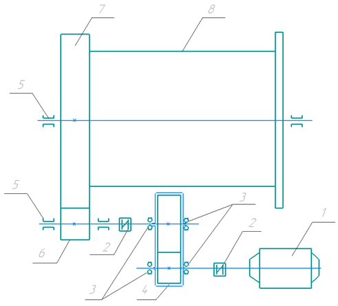
1-Electric motor; 2- Couplings; 3 -Friction bearings; 4 - Cylindrical reducer; 5 -Sliding bearings; 6 –Drive gear; 7-Tooth ring; 8-Mill housing
Fig. 1. Kinematic diagram of a drum ball mill
Table 1 below provides an overview of the three approved heading levels and should be used as a reference when preparing the manuscript.
Table 1. Table 1. Initial data for STS calculation
| Heading level | Example | Font size and style |
| Transmission ratio | u | 7,59 |
| Teeth number of:- gears- gear wheel | z | 29220 |
| Calculated torque on the gear | Tg [Nm] | 39226, 6 |
| Gear rotation frequency | n [rpm] | 136,6 |
| Module | m [mm] | 20 |
| Tooth length of:- gear- cogwheel | bg [mm] b [mm] | 440430 |
| Interaxial distance | aw [mm] | 2490 |
| Pressure angle | α [deg] | 20 |
| Profile shift coefficient | x | 0 |
The gear, toothed wheels, and welded tooth are made of steel 30X, and steel 30 HGSA, steel 35GL, respectively. The mechanical characteristics of the gear transmission are taken from [43, 44, 45] and are presented in Table 2.
Table 2. Mechanical characteristics of gear and clad tooth
| Parameters | Gear | Clad tooth | Crown |
| Modulus of elasticity (E), Young's modulus [MPa] | 2.08 × 10⁵ | 2.15 × 10⁵ | 2.12 × 10⁵ |
| Poisson's ratio | 0.29 | 0.29 | 0.29 |
| Compressive strength [MPa] | 880 | 1080 | 515 |
| Tensile strength [MPa] | 880 | 1080 | 515 |
| Density [g/cm3] | 7.820 | 7.850 | 7.830 |
| Shear modulus [MPa] | 80620 | 83333.330 | 82170.54 |
| Yield strength [MPa] | 685 | 830 | 310 |
The contact stresses in the meshing pole are determined by the following formula:
| (1) |
Where:
Z_H - contact ratio factor (tooth shape), Z_H=2.5;
Z_M - elastic coefficient (material properties), n this case Z_M =192 MPa;
Z_ε - contact length factor (tooth overlap), Z_ε =0.9 for straight teeth .
W_Ht - specific calculated circumferential force, which is determined by the following formula:
| (2) |
Where:
F_t is the tangential force applied to the gear tooth, which depends on the transmitted torque and the pitch circle radius of the gear, N;
b_w - the width of the gear rim or the working surface of the tooth, which affects load distribution, mm;
K_Hα - dynamic load factor (along the line of action), which takes into account the change in load due to engagement errors and other dynamic factors;
K_Hβ - coefficient of load across the width of the gear rim, which adjusts the load calculation taking into account the uneven distribution of load across the tooth width;
K_Hν – coefficient of bending load (or other types of deformation) that includes additional loads associated with the elastic deformations of the teeth.
Circumferential force applied to the gear tooth:
| (3) | ||
Where:
T_g - is the transmitted torque on the gear, N·mm.
d_g - pitch diameter of the gear, the diameter of the imaginary circle along which the load is transmitted through meshing, mm.
The pitch diameter of the gear is calculated using the following formula:
Substituting the value into formula (3), we calculate the circumferential force applied to the gear tooth:
As a result of the installation, the specific calculated circumferential load:
Then the design contact stresses are:
 |
Next, we will calculate the strength of the gear transmission under bending. For this, we will determine the calculated bending stress at the base of the tooth of the gear and the wheel using the formula:
| (4) |
where Y_F is a coefficient that takes into account the shape of the tooth profile, which is determined by the following formula for wheels with external teeth:
 |
(5) |
where z_g =29 and z_w =220 are the number of gear and wheel teeth, respectively;
Y_b - coefficient takes into account the inclination of the tooth line, Y_b =1 is for straight teeth;
Y_e - coefficient accounting for tooth overlap, for straight teeth Y_e =1.
Coefficient accounting for additional dynamic load on the tooth K_Fu »1.
W_Ft - specific design circumferential load, N/mm.
After substitution, we calculate the coefficient that takes into account the shape of the tooth profile for the gear by formula (5):
 |
The coefficient that takes into account the shape of the tooth profile for the wheel:
The specific design circumferential load is calculated from the following formula:
| (6) |
where F_t - is the circumferential force applied to the gear tooth, which was calculated by formula (3);
b - gear or wheel ring width, mm;
K_Fa- coefficient that includes the load distribution between the teeth, for straight teeth K_Fa = K_Ha = 1.
K_Fb = K_Hb = 1.06 - coefficient that includes the uneven distribution of load across the width of the gear rims.
As a result of the substitution, the specific calculated circumferential loads on the teeth of the gear and wheel are:
Calculated local bending stresses at the base of gear and wheel tooth:
2.1 Numerical modeling using the finite element method (FEM)
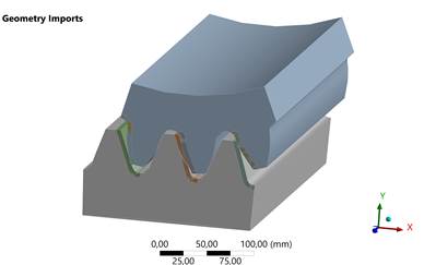
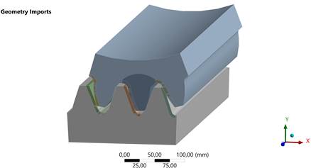
Following an analytical determination of the gear and wheel's contact and bending stresses, we use the numerical approach to ascertain them. The application of modern computer-aided engineering (CAE) systems provides the opportunity to effectively assess the behavior of a digital product model and ensure its functionality based on computational methods of elasticity theory, without significant time and financial costs. The FEM has a key advantage that allows for the precise distribution of displacements and stresses in complex mechanical systems. In the study of the stress-strain status (SSS) of gear transmissions, the finite element method is the most effective tool for analyzing the interaction between the tooth profile of the gear (working surface) and the wheel rim (contact surface). At the same time, the mechanical properties of materials, geometric parameters such as the tooth module, contact angle, crown width, tooth shapes, load application characteristics, and boundary conditions are considered. For the finite element method study in the ANSYS application program, the biomaterial method was chosen (Stress and mesh stiffness evaluation of biomaterial spur gears), because the welded tooth profile consists of the main gear material and a welded layer that has higher hardness [1]. The biomaterial analysis method is a numerical analysis method that allows for different materials of the tooth (base and overlay), which allows for more accurate modeling of their behavior under load. Accordingly, the tooth structure becomes biomaterial, and each material has its own strength characteristics and elastic moduli that need to be considered. To optimize computational resources and reduce machine calculation time in the three-dimensional model, only three pairs of teeth of the gear and wheel are considered (Figure 2). The selected pairs of teeth ensure sufficient analysis accuracy, as the interaction of teeth in the meshing zone is repeated around the entire circumference. The use of a full model of the gear and pinion significantly increases the calculation time without providing fundamentally new data for the local analysis of the stress-strain status (SSS). Thus, simplifying the model allows for focusing on the study of critical tooth interaction zones while maintaining the accuracy of the results. A similar modeling method is described in works [3, 4, 12, 16, 21, 26, 35, 38, 39, 40], where it is shown that analysis at the engagement pole provides accurate results in assessing local stresses and deformations.
a)
b)
Fig. 2. Three-dimensional model of a gear pair: a) with solid teeth; b) with a clad tooth
We will configure the contact (Frictionless) to replicate the engagement between the wheel's (contact surface) and the gear's (target surface) tooth profiles (Figure 3).
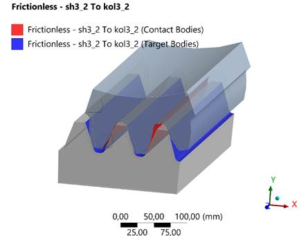
Fig. 3. Contact between the tooth profiles of the gear and the wheel
During the study, the bearing connection points were additionally adjusted (Fig. 4). To transmit the torque, the gear was secured as a hinge connection with one rotation in the plane, while the wheel was fixed in a clamped state. This made it possible to firmly attach the welded tooth under study, allowing for a thorough examination of its stress-strain condition. In the absence of clamping, the tooth would be in constant motion, leading to its rotation and sliding, which would hinder a comprehensive analysis of the stress-strain state.
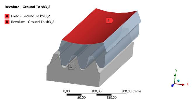
Fig. 4. Locations of the gear and wheel connections
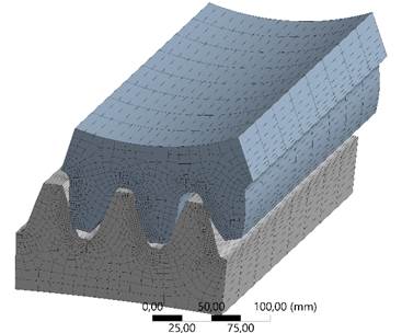
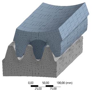
For conducting CAE analysis, a hexahedral finite element mesh was chosen because it provides higher modeling quality compared to a tetrahedral mesh. Hexahedral elements, due to their shape, allow for a smooth and stable mesh in critical areas, such as the tooth root, which increases the accuracy of results and minimizes the risk of singularities. This is especially important for accurately modeling stresses in high-load areas and reduces the likelihood of data distortions.
Moreover, the hexahedral mesh requires fewer computational resources compared to the tetrahedral mesh at equivalent accuracy, which reduces the analysis time [46]. A similar type of mesh was used in the studies [47] to obtain reliable data on the stress distribution in the tooth root zone.
To ensure high accuracy of the results, a dense FEM mesh was created [47, 48]. The "Contact Sizing" command was used with the element size in the contact area of the welded tooth and gear set to 2 mm, which significantly improves the mesh quality in the contact area. The application of such a method ensured more detailed modeling, improving the distribution of elements in the area of the welded tooth and its surroundings. As a result, the finite element mesh for the gear included 1,330,087 nodal points and 457,372 elements (Fig. 5).
The manuscript should include no more than three levels of headings to ensure clarity and consistency. All figures and tables must be embedded within the main text, positioned close to where they are first referenced. Tables must be submitted in an editable format (e.g., created using the table function in Word or Excel). Images of tables (e.g., screenshots or scanned versions) will not be accepted.
a)
b)
Fig. 5. Finite element mesh of a gear pair: a) with solid teeth; b) clad tooth
The calculated torque on the gear Tg=39226.6 Nm and the gravitational force is applied in the boundary conditions. Its change over time or magnitude can be used for the step. Let's convert the rotational frequency n = 136.6 rpm to angular w:
|
ω=2πn/60=2π⋅136.6/60≈14.3 rad/sec |
Considering that this is the contact between a gear and a pinion, the problem is nonlinear, and the step increment is critically important. We adjust the torque changes from 0 to 39226.6 Nm to set the main step. Then the main step can start with ΔT=10% of the maximum moment, i.e., ΔT= 3922.7 Nm. For each step, the load is divided into several sub-steps. In our case, we take 393.3 Nm. We also enable the Automatic Time Stepping option to reduce the step size if necessary. This is useful for problems with nonlinear contacts. After the calculation has been solved. Step adjustment allows for the gradual increase of moment Tш to avoid numerical errors; to account for nonlinear contact conditions between teeth and to reduce the likelihood of convergence loss.
To study the stress-strain state of the base metal of the gear with a clad tooth at the pit diameter, we will mark points 1 and 2 (Fig. 6).
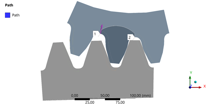
Fig. 6. The joint line of the welded tooth with the base metal
3 Results and discussion
In the convergence window, we can observe convergence in all iterations (Fig. 7). Convergence in ANSYS (as in any other numerical method) is a key aspect where the given problem approaches a stable solution of the equations describing the physical issue. This is crucial for nonlinear problems (contact, plasticity, large deformations, etc.), where the solution requires an iterative approach.
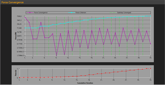
Fig. 7. Results of the convergence calculations
In the upper graph (Fig. 7) (Force Convergence), the purple lines show how the difference in force reactions changes between iterations. This is a key indicator of convergence for solving the problem. The fluctuation of this line is considered normal for nonlinear problems, especially in the presence of contacts or complex materials. Despite the fluctuations, each sub-step converges at the end, as confirmed by the green vertical lines. Here, a specific convergence criterion is shown by the blue line (Force Criterion). The criterion level is sufficiently low to guarantee high accuracy in the outcomes. The step is said to be convergent when the purple line falls below the blue line. It is important that the purple line drops below the blue line at each sub-step, which means that convergence has been achieved.
The green vertical lines (Substep Converged) indicate that the substeps have converged. In the lower graph (Cumulative Iteration vs Time), the red dots show how the solution time changes with the increase in the number of iterations.
Below are the diagrams showing the contact stress at the contact pole (Figure 8) and the bending stress at the base of the gear tooth (Figure 9).
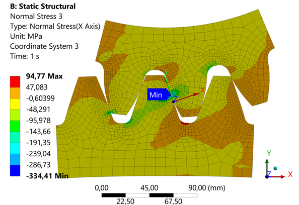
Fig. 8. Contact stress at the contact pole
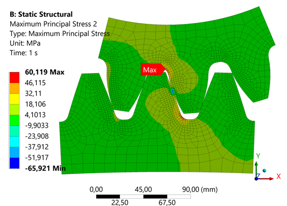
Fig. 9. Bending stress at the base of the tooth
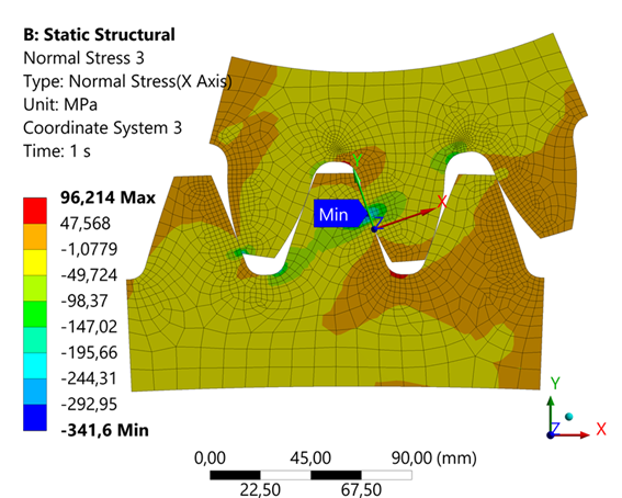
Fig. 10. Contact stress at the contact pole with the welded gear tooth
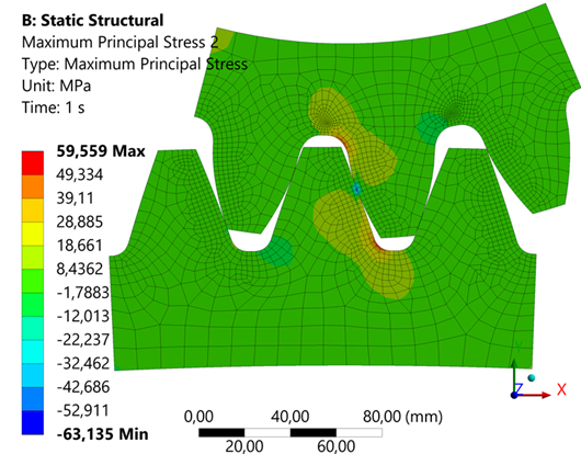
Fig. 11. Bending stress at the base of the tooth with a welded gear tooth
Figures 12 and 13 depict the contact and bending stresses at the Mises-defined connections between the welded tooth and the base metal of the gear.
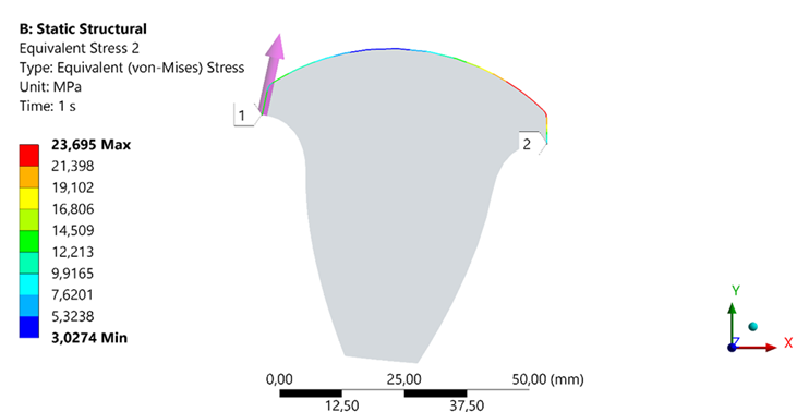
Fig. 12. Stress along the Misese at the junction of the clad tooth
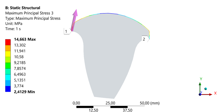
Fig. 13. Bending stress at the junction of the clad tooth
In the models presented in the ANSYS software, a study of the involute profile of the surfacing tooth during engagement with the mill crown was conducted. It was found that at an angle y =33° (Fig. 14, a), the welded tooth engages. As the angle increases to y = 43° (Fig. 14, b), the welded tooth exits the engagement zone. At other values of the tooth position angles (less than y =33° and greater than y=43°), the stress values are minimal. This parameter, called the tooth position angle, characterizes the angular range within which active engagement between the studied teeth takes place.
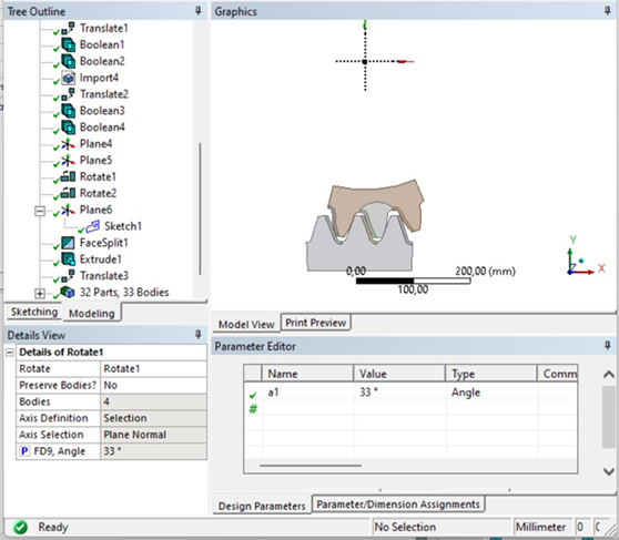
a) at the moment of attachment
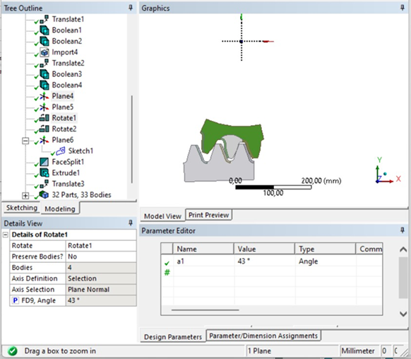
b) exit from entanglement
Fig. 14. Positions of the welded tooth in engagement
We conduct a comparative analysis of contact stresses (Fig. 15) and bending stresses calculated through analytical and numerical modeling (Fig. 16), as well as at the contact points of the tooth's overlay layer with the gear's base metal (Fig. 17).
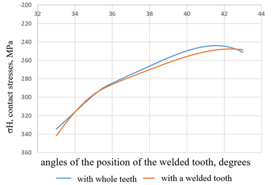
Fig. 15. Results of the contact stress calculation
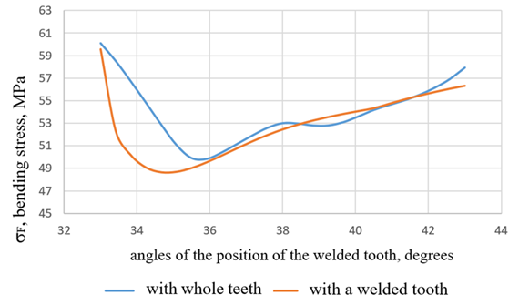
Fig. 16. Results of the bending stress calculation
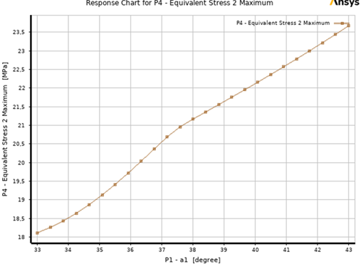
Fig. 17. Equivalent stress at the junctions of the base metal and the deposited tooth as a function of the tooth position angle
4 Conclusions
- The graph (Fig. 7) shows that the problem converges, but with oscillations. This behavior is characteristic of complex nonlinear problems, where stresses are determined and require iterative refinement. Fluctuations in convergence are due to the complexity of the model, which includes contact interaction and material with nonlinear principles.
- The analytically calculated maximum contact stress is -348 MPa, whereas the numerical simulation in ANSYS showed a result of -334 MPa (Fig. 8). A 4% deviation indicates high calculation accuracy.
- The calculated bending stress at the base of the tooth is 61.6 MPa, while the simulation in ANSYS yields 60.119 MPa (Fig. 9). The deviation within 2.6% confirms the reliability of the chosen calculation method.
- At the contact pole of solid teeth, the contact stress is -334.41 MPa (Fig. 8), while for welded teeth it is 341.6 MPa (Fig. 10). This indicates the possibility of using welded teeth in cylindrical low-speed transmissions, which leads to a sufficient level of stress in the open transmission.
- The basis of the tooth is of particular scientific interest, as this area is critical in terms of maximum bending stresses. The base of the tooth is of particular scientific interest, as this area is critical in terms of maximum bending stresses. The bending stress for the solid tooth is 60.119 MPa (Fig. 9), while for the welded tooth it is 59.559 MPa (Fig. 11).
- The comparison of contact and bending stresses shows high correspondence between the analytical and numerical data. The deviations are 4% for contact stresses (Fig. 15) and 2.6% for bending stresses (Fig. 16), indicating the accuracy of the model application and its relevance for engineering analysis.
- The analysis of bending stress curves at the junctions of the base metal with the welded tooth (Fig. 17) shows their prevalence for both solid and welded teeth; however, the minimum curvature for the welded tooth is shifted to the area of the tooth position angle of 35° and amounts to 48.6 MPa. The shift is associated with the redistribution of stresses caused by the structural features of the deposited material and static stresses. This change will affect the operational characteristics of the gear wheel, including its performance and resistance to cyclic loads.
- The analysis of the dependence of the equivalent stress (on the Y-axis, in MPa) on the angle of the position of the welded tooth in the engagement pole (on the X-axis, in degrees) shows their prevalence for welded teeth. At a tooth position angle y = 33°, the equivalent stress is approximately 18 MPa, which can be considered as the baseline stress level at which changes begin. The increase in stress in the range from 33° to 43° occurs almost linearly, indicating a stable functional dependence between the tooth position angle and stress. The maximum value of the equivalent stress is observed at an angle y = 43°, reaching a level of 23.5 MPa, representing a 30% increase relative to the baseline value. This increase in stress reflects the phenomenon of load redistribution due to the change of contact between the surfaces.
- Results from this method of analyzing the clad tooth's angular position in the meshing are relevant and distinct.
- Numerical methods, such as simulations in Ansys Workbench, allow a more detailed analysis of stress distribution and identification of critical zones in the gear.
- The proposed calculation methodology can be used to design and optimize gears, including those with clad teeth.
Acknowledgements
No external funding was received.
References
- Smailova, B. K., Buzauova, T. M., Bartenev, I. A., & Davletova, K. Restoration of large modular teeth of ball mill gears by electro-slag surface. Journal of Applied Engineering Science 2024, 22(2), 483–491. https://doi.org/10.5937/jaes0-49369.Kantute, Sh. V., & Wankhede, P. R. Design and analysis of stress for spur gear. International Journal of Advance Scientific Research and Engineering Trends 2020, 5(12), 6–10.
- Bekheet, N. Involute gear tooth stresses analysis using finite element modeling. American Scientific Research Journal for Engineering, Technology, and Sciences 2017, 34(1), 269–284.
- Wen, Q., Du, Q., & Zhai, X. An analytical method for calculating the tooth surface contact stress of spur gears with tip relief. International Journal of Mechanical Sciences 2019, 151, 170–180. https://doi.org/10.1016/j.ijmecsci.2018.11.007.
- Vouaillat, G., Noyel, J.-P., Ville, F., Kleber, X., & Rathery, S. From Hertzian contact to spur gears: Analyses of stresses and rolling contact fatigue. Mechanics & Industry 2019, 20, 626. https://doi.org/10.1051/meca/2019064.
- Azemi, F., Pllana, G., Terbunja, M., & Maloku, B. Stress-strain analysis of the spur gear of the gearbox reduction of the working wheel of the excavator SCHRS 1300 24/5.0 using CAD/CAE software. International Journal of Mechanical and Production Engineering 2016, 4(5), 24–28.
- Mahendran, S., Eazhil, K. M., & Senthil Kumar, L. Design and analysis of composite spur gear. RSIS 2014,1(6), 42–53.
- Jasem, M. A., & Krauinsh, P. Ya. Analysis of the stress-strain state under static load of face wave kinematic reducer. Bulletin of Irkutsk State Technical University 2019, 23(5), 854–862. https://doi.org/10.21285/1814-3520-2019-5-854-862.
- Kantute, Sh. V., & Wankhede, P. R. Design and analysis of stress for spur gear. International Journal of Advance Scientific Research and Engineering Trends 2020, 5(12), 6–10.
- Ahmed, B. A. Identifying the influence of dimensional parameters on the stresses and deformations of two helical gears. Eastern-European Journal of Enterprise Technologies 2022, 5/7(119), 76–83. https://doi.org/10.15587/1729-4061.2022.266261.
- Gajender, V. R., & Jeyapoovan, T. Design and stress-strain analysis of composite spur gear in the automobile. International Journal of Engineering Sciences & Research Technology 2016, 5(5), 144–156. https://doi.org/10.5281/zenodo.51011.
- [Ram, B. S., & Sir, P. Design modeling & stress-strain analysis of composite spur gear used in automobile. International Journal of Engineering Research & Technology (IJERT), 2018, 7(5), 161–172.
- Husaini, & Dawud, D. M. Numerical analysis of stress causing fracture failure in the gear transmission system applied on agricultural machinery equipment. Journal of Physics: Conference Series, 2019, 1351(1), 012021. https://doi.org/10.1088/1742-6596/1351/1/012021.
- Manickaraj, K., Rajesh Kumar, T., & Subhash, SStress analysis of spur gear drive using finite element method by varying pressure angle. International Journal of Innovative Research in Technology 2014. 1(9), 113–116.
- Singh, J. P. Stress analysis of spur gear using Ansys. International Journal of Novel Research and Development 2023, 8(6), 113–135.
- Thu, M. P., & Min, N. L. 2018. Stress analysis on spur gears using ANSYS Workbench 16.0. International Journal of Science and Engineering Applications, 7(8), 208–213.
- Ramakrishna, Ch., Anil, Y., Kumar, M. N. V. R. L., & Kiran, R. U. Typical stress & deflection analysis of spur gear in spur gear assembly. International Journal of Science Technology & Engineering 2016, 3(2/3), 192–207.
- Franulovic, M., Markovic, K., & Herceg, Z. Stress-strain response in gears tooth root due to low cycle fatigue. MATEC Web of Conferences, 2019. 287, 02002. https://doi.org/10.1051/matecconf/201928702002.
- Zorko, D., Tavčar, J., & Duhovnik, J. The influence of the tooth profile shape on the stress-strain state in the gear. Machines. Technologies. Materials, 2018, 4, 153–156.
- Ingole, G. B., Wadkar, S. B., & Watwisave, D. S. Analysis of stress relieving features of asymmetric spur gear. International Journal of Innovation in Engineering, Research and Technology, ICITDCEME’15 Conference Proceedings, 2015 (37). 1–6.
- Dong, Sh., Luan, Zh., & Ma, Ch. Finite element analysis of single pair gear tooth root crack. 7th International Symposium on Test Automation and Instrumentation, 2019(23), 9166–9169.
- Vigneshwaran, K., Shanmugam, D., & Balasuthagar, C. Experimental and analytical stress analysis of spur gear. 3rd International Conference on Advances in Mechanical Engineering (ICAME) 2020. https://doi.org/10.1088/1757-899X/912/2/022043.
- Mozharovsky, V. V., Kirhintsava, S. V. Calculation of the stress-strain state of gear teeth made of composite and functional gradient materials. Problems of Physics, Mathematics and Technics 2023, 1(54), 31–37. https://doi.org/10.54341/20778708_2023_1_54_31.
- Ramachandra, P. M., Sutar, S., & Mohan Kumara, G. C. Stress analysis of a gear using photoelastic method and finite element method: Review. International Conference on Materials and Sustainable Manufacturing Technology, 65(8), 3820–3828. https://doi.org/10.1016/j.matpr.2022.06.579.
- Velgodskaia, T. V., Ivanov, V. V., & Gadzhiev, I. A. Analysis of the stress-strain state of the gear in the traction gearbox of the 2TE10L locomotive. Meždunarodnyj naučno-issledovatel'skij žurnal, 2012, 5, 82–85.
- Li, Q., & Xie, L. Analysis and optimization of tooth surface contact stress of gears with tooth profile deviations, meshing errors, and lead crowning modifications based on finite element method and Taguchi method. Metals, 2020, 10(1370), 1–29. https://doi.org/10.3390/met10101370.
- Matejic, M., Blagojevic, M., Disic, A., Milovanovic, M., & Miletic, I. A dynamic analysis of the cycloid disc stress-strain state. Applied Sciences 2023, 13(4390). https://doi.org/10.3390/app13074390.
- Gonzalez-Perez, I., & Fuentes-Aznar, A. Implementation of a finite element model for stress analysis of gear drives based on multi-point constraints. Mechanism and Machine Theory 2017, 117, 35–47. https://doi.org/10.1016/j.mechmachtheory.2017.07.005.
- Wang, J., Wang, Y., & Huo, Z. 2013. Finite element residual stress analysis of planetary gear tooth. Advances in Mechanical Engineering 2013, 12 pages. http://dx.doi.org/10.1155/2013/761957.
- External spur gear root bending stress: A comparison of ISO 6336-2006, AGMA 2101-D04, ANSYS finite element analysis and strain gauge techniques.
- Husaini. 2019. Numerical analysis of stress causing fracture failure in the gear transmission system applied on an agricultural machinery equipment. Journal of Physics: Conference Series, 1351(1), 012021. https://doi.org/10.1088/1742-6596/1351/1/012021.
- Patil, S. S., Karuppanan, S., & Atanasovska, I. Experimental measurement of strain and stress state at the contacting helical gear pairs. Measurement 2016, 82, 313–322. https://doi.org/10.1016/j.measurement.2015.12.046.
- Patchigolla, R., & Singh, Y. P. Finite element analysis of large spur gear tooth and rim with and without web effects - Part I. ASEE Gulf-Southwest Annual Conference Southern University and A & M College, 2006.11 pages.
- Gajender, V. R., & Jeyapoovan, T. Design and stress-strain analysis of composite spur gear in automobile. International Journal of Engineering Sciences & Research Technology 2016, 5(5). https://doi.org/10.5281/zenodo.51011.
- Creţu, S., Pop, N., & Cazan, S. Tooth contact analysis of spur gears. Part 1: SAM analysis of standard gears. MATEC Web of Conferences, 112, 07015. https://doi.org/10.1051/matecconf/201711207015.
- Nikolić, V., Dolićanin, Ć., & Dimitrijević, D. Dynamic model for the stress and strain state analysis of a spur gear transmission. Strojniški vestnik - Journal of Mechanical Engineering 2012. 58(1), 56–67. https://doi.org/10.5545/sv-jme.2009.128.
- Brailko, N. N., Tkachenko, I. M., Kovalenko, V. V., Lemeshko, A. V., Fenko, A. G., Kozak, R. V., & Kalashnikov, D. V. Investigation of stress-strain state of “restoration & tooth” system in wedge-shaped defects by computed modeling method. Wiadomości Lekarskie 2021. 74(9), 1. https://doi.org/10.36740/WLek202109116.
- Singh, J., & Tyagi, M. R. Analysis of stresses and deflections in spur gear. International Journal of Mechanical Engineering and Technology (IJMET), 2017. 8(4), 461–473.
- Hochrein, J.-F., Otto, M., & Stahl, K. Face gear drives: Nominal contact stress calculation for flank load carrying capacity evaluation. Mechanism and Machine Theory 2024, 195, 105573. https://doi.org/10.1016/j.mechmachtheory.2024.105573.
- Czakó, A., Řehák, K., Prokop, A., Rekem, J., Láštic, D., & Trochta, M. Static transmission error measurement of various gear-shaft systems by finite element analysis. Journal of Measurements in Engineering 2024, 12(1). https://doi.org/10.21595/jme.2023.23843.
- Vinogradov, B. V., & Fedin, D. A. Features of calculating open gear drives for strength. Bulletin of NTU "KPI", 2015. (34), 19–25.
- Buzauova, T. M., Sarbaev, D. A., Smailova, B. K., Toleubayeva, Sh.. Analysis of the stress-strain state of the surfaced tooth in the T-FLEX CAD application program. Material and Mechanical Engineering Technology 2024, (4), 17–24. https://doi.org/10.52209/2706-977X_2024_3_17.
- GOST 21354–87. External involute gear transmissions. Moscow: Standards Publishing House, 1987. 129 pages.
- GOST 4543–71. Rolled products made of alloyed structural steel. Moscow: Standards Publishing House, 2008. 41 pages.
- GOST 19281–2014. High-strength rolled products. Moscow: Standartinform, 2021. 71 pages.
- GOST 380–2005. Carbon steel of ordinary quality. Moscow: Standartinform, 2009. 11 pages.
- More, S. T., & Bindu, R. S. Effect of mesh size on finite element analysis of plate structure. International Journal of Engineering Science and Innovative Technology, 2015, 4(3), 181–185.
- Pisarenko, G. S., Agarev, V. A., & Kvitka, A. L. Soprotivlenie materialov (5th edition). Kiev: Vysshaya shkola. 1986; pp. 32–58.
- Iosilevich, G. B. Stress concentration in machine parts. Moscow: Mechanical Engineering. 1981. 320 pages.
Conflict of Interest Statement
The authors declare that there is no conflict of interest regarding the publication of this paper.
Author Contributions
Data Availability Statement
No dataset is associated with this study.
Supplementary Materials
There are no supplementary materials.